6.2
Power supply
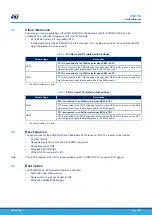
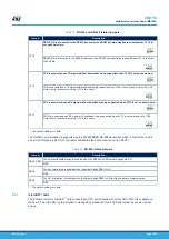
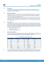
The STM32G0C1E-EV Evaluation board is designed to be powered by a 5 V DC power supply and is protected
from the wrong power plug-in event.
Thanks to the JP24 jumper, it is possible to configure the mother board to use any of the following four sources for
the power supply:
JP24 = E5V
5 V DC power adapter connected to CN20, the power jack on the board. The external power supply is provided to
the board.
JP24 = STLK (Default configuration)
5 V DC power with 500 mA limitation from CN5, the USB Micro-B connector of ST-LINK/V2-1. If the USB
enumeration succeeds, the ST-LINK PWR_EN pin is set to zero, which enables an STMPS2141STR power
switch, thus providing 5 V power to the board. This power switch also features a current limitation to protect the
PC in case of short-circuit on the board. If an overcurrent (more than 500 mA) happens on the board, the LD8
LED lights up.
JP24 = VUSB
5 V DC power from USB Micro-B connector of ST-LINK/V2-1, CN5 pin 1 (V
BUS
) directly, without overcurrent
protection
JP24 = D5V
5 V DC power from CN3 or CN10 connectors, the extension connectors for a daughterboard power source
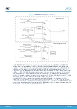
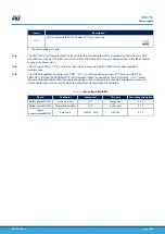
The UCPD daughterboard uses its own 19 V power adapter to support USB PD. In this case, the mother board
uses D5V from the UCPD daughterboard to supply all circuits on the STM32G0C1E-EV Evaluation board. D5V of
the UCPD daughterboard has three sources as below:
•
19 V DC power adapter connected to MB1352_CN3 on the UCPD daughterboard
•
Power from USB Type-C
®
port1 MB1352_CN7 on the UCPD daughterboard
•
Power from USB Type-C
®
port2 MB1352_CN5 on the UCPD daughterboard
19 V DC power adapter and USB Type-C
®
port1 sources are automatically selected by a circuit (MB1352_D8 and
MB1352_T10 on the UCPD daughterboard).
Caution:
In case of development based on the boards, note that unexpected high voltage may appear in CN7 when
plugging in 19 V power. So when using a 19 V power adaptor, apply default demonstration configuration with the
boards, or refer to steps
in MB1352 schematic, and install protection on the software side
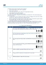
[1] Steps:
1.
DCDC_EN detects its voltage to ensure PSU 19V exists.
2.
PWM_CTL provides about 0.8 V level before DCDC_EN=1.
3.
DCDC_EN=1, then PWM_CTL changes to provide PWM waveform by 0 and open-drain.
[2] Protection on the software side:
•
Refer to
/* SAFETY PROTECTION CODE BEGIN */
section in
main.c
of USB_Host applications. This
file can be found in STM32Cube_FW_G0_1.4.0 in
.
UM2783
Power supply
UM2783
-
Rev 1
page 12/59


