- 29 -
CLRS Series RS485 Closed Loop Stepper Drive User Manual
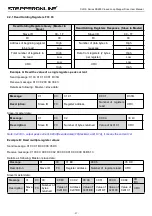
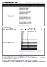
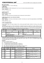
Message Example
Conditions: Drive ID is 1, motor is stationary.
(1) Mapping
Master→Slave:
01 10 0F 10 00 0A 00 00 01 00 09 00 A1 01 91 01 67 01 73 02 33 02 43 60 2E 62 03 4B 43
Slave → Master:
01 10 0F 10 00 0A 42 DF
(2) Read and write
Master→Slave:
01 03 0F 00 00 0A C6 D9
Slave → Master:
01 03 14 27 10 05 87 00 0F 00 3C 00 FA 00 03 0F A0 00 5A 00 01 00 00 00 56 F4
(3) Mapping parameter save instruction 0x2244
Master→Slave:
01 06 18 01 22 44 C6 39 (Note: Write 0x2244 to 0x1801, the function is to save the mapped address into EEPROM)
Slave → Master:
01 06 18 01 22 44 C6 39
4.6 S-code Application
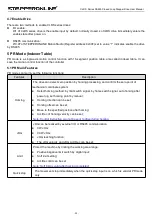
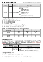
S-code (status code) is the status indicator of the currently executed PR path, whether it is running, or the path is
completed.
In a normal path program, no matter which path is completed, the drive will output the run status uniformly, but it is
difficult to identify which path. The S-code function can help to identify the specific path number and running status,
or read the value of Pr8.38(0x601C). Each PR path can set an S-code, i.e. each path has a dedicated S-code
register, the exact S-code is user-defined according to the table format below.
Size S
High 8 bits
Lower 8 bits
# Bit
bit15
bit8-10
bit7
bit0-2
Description
Whether the S code is valid at the time
of completion:
0: Invalid, keep last value
1: Effective (Recommended)
S-code
at
completion
Whether the start S code is
valid or not:
0: Invalid
1: Effective (Recommended)
S-code at start -up
bit7 and bit15 are set to 1.
The rest of the unused bits are 0, such as bits 11-14, bits 3-6.
CLRS series drivers have only 3 outputs, and the S-code can only use 3 bits, each bit corresponds to an output.
Therefore, there are only 8 output combinations (000, 001, 010, 011, 100, 101, 110, 111), and these 8 states can be
set freely, depending on the requirements.
Example:
Here is an example of paths 1-4:
All output ports are set to normally open.
“1” indicates that the output optocoupler is switched on.
“0” indicates that the output optocoupler is switched off.
“001” means that output port 1 is on, and outputs 2 and 3 are not on.
Pr8.28: S-code current output value; register address: 0x601C.
Path
number
S-code at
completion
bit8-10
S-code at
start-up
bit0-2
S code setting value
Remarks
Path 1
001
000
Binary: 1000 0001 1000 0000
Hexadecimal: 0x8180
At start-up: No level at all three outputs
Completion: Output port 1 has level, PR8.28=1
Path 2
011
010
Binary: 1000 0011 1000 0010
Hexadecimal: 0x8382
At start-up: Output port 2 has level
On completion: Outputs 1 and 2 have levels,
PR8.28 = 3
Path 3
101
100
Binary: 1000 0101 1000 0100
Hexadecimal: 0x8584
At start-up: Output port 3 has level
On completion: Outputs 1 and 3 have levels,
PR8.28 = 5
Path 4
111
110
Binary: 1000 0111 1000 0110
Hexadecimal: 0x8786
At start-up: Outputs 2 and 3 are level
When finished: output ports 1. 2. 3 are level,
PR8.28=7

