ROLLBOTMICRO
24
Hardware Introduction
6.1 Overview
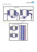
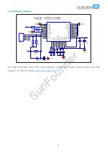
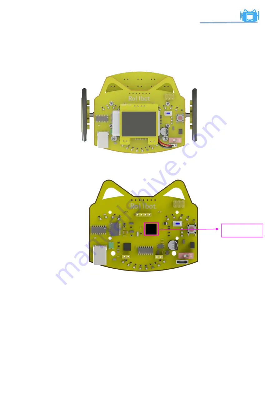
The schematic diagram is mainly shown for several modules: main control, boost/step-up
convertor, power selector, USB interface, motor driver, LED indicator, signal collection and OLED
display.
6.2 Main Control
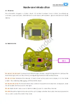
Pin A0, A1, A2, A3, &A7
: Connect the infrared sensor module. Apply PID algorithm to achieve the
line following function of the robot by distinguishing the black and white surfaces.
Pin SCL & SDA
: Simulates the intensity of black lines by the sensor and display it on the OLED
screen, thus enabling debugging with the OLED screen.
Pin D4, D7, D5, & D6
: Pin D4 and D5 for the control of the left motor's direction and speed, when
Pin D7 and D6 for the motor on the right.
Pin A6
: Read its AD value so as to tell the battery power in a real-time manner.
Pin D10
: Read the high and low level of the pin to judge whether the button has been pressed or
not, so as to control the start of the robot.
MCU
SunFounder


