Page 1
Apr-21-2016 DI-602A 320 DS (NZ313)_UL_April 2016
Texmate, Inc. Tel. (760) 598-9899 • www.texmate.com
A powerful, intelligent, 16-digit Programmable Meter Controller (PMC)
with modular outputs, input signal conditioning and advanced software
features for monitoring, measurement, control and communication applications.
DI-602AE & DI-602AT5C
Programmable Meter Controllers
Tiger 320 Series PMCs
Two 6 Digit 0.39”
Alphanumeric LED Displays
in a 1/8 DIN Case
TIGER FAMILY
Table of Contents
✔
TIGER FAMILY
: More than 120 different Plug-in
I-Series Input Signal Conditioners are approved for
the Tiger Family of meters.
See
I-Series Input Signal Conditioning Modules
Guide
(Z87) for an up-to-date list.
Input Module Compatibility
• The Tiger 320 Operating System supports an easy to use
PC based Configuration Utility Program (which can be down-
loaded FREE from the Texmate website) and programming
from front panel buttons.
• The T Version supports custom macro programs that can
be easily produced with the Tiger 320 Macro Development
System (available FREE on the Texmate website). The
Development System enables programs to be written in
BASIC, which can utilize any combination of the hundreds of
functions and thousands of registers embedded in the Tiger
320 Operating System.
• Red, green, or red/green 14-segment, 0.39” high LEDs with
full support for 14-segment alphanumeric text.
• Brightness control of LED display from front panel buttons.
• Modular construction with more than 120 interchangeable
input signal conditioners and more than 25 interchangeable
I/O modules.
• Up to 4 input channels with cross channel math for multi-chan-
nel processing.
• For applications where sensor excitation is required, mod-
ules are provided with 5V, 10V or 24 V DC voltage outputs.
• On demand tare, calibration and compensation can be initi-
ated by the front panel program button.
• Autozero maintenance for super stable zero reading is pro-
vided for use in weighing applications.
• Programmable input averaging and smart digital filtering for
quick response to input signal changes.
• Display text editing. Customize display text for OEM applica-
tions.
• Scrolling display text messaging on T meters with macros.
• Auto-sensing high voltage or optional low voltage AC / DC
power supply.
• Serial output options include RS-232, RS-485, ModBus,
Ethernet, or direct meter-to-meter communications.
• Single or dual 16-bit Isolated Analog Outputs. Programmable
0~4 to 20mA or 0 to 10V for retransmission, 4-20mA loops
to drive valve actuators, remote controllers & displays, multi-
loop feedback and PID output. Scalable from 1 count to full
scale.
• Dual independent totalizers to integrate input signals.
• 6 super smart, independently programmable setpoints with 8
selectable functions, including latching, deviation, hysteresis,
register resetting, tracking and dual PID. Plus 7 programma-
ble timer modes on all 6 setpoints.
• Setpoint tracking, setpoint latching and manual relay reset.
• Setpoints activated from any input, any register in the meter
or from any digital input.
• Plug-in I/O modules include electromechanical or solid state
relays, logic outputs or open collector outputs. 6 inputs & 16
outputs of opto-isolated I/O can be connected to an external
DIN Rail terminal block module.
• Internal program safety lockout switch to prevent tampering.
• Peak & valley (max & min) with front panel recall and reset.
• Real time clock with 15 year Lithium battery backup.
• Data logging within the meter (up to 4000 samples with date/
time stamp).
• Optional NEMA-4 front cover.
• UL Listed
General Features
General Features . . . . . . . . . . . . . . . . . . . 1
Specifications. . . . . . . . . . . . . . . . . . . . . 2-3
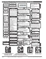
Block Diagram of Tiger 320 Structure . . . 4
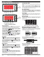
Controls & Indicators. . . . . . . . . . . . . . . 6-7
Front Panel Configuration & Setup. . . . . . 8
Front Panel Programming Codes. . . . 9-10
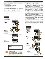
Initial Setup Procedures . . . . . . . . . . 11-12
Display Brightness. . . . . . . . . . . . . . . . . . 12
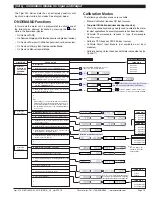
Calibration Modes . . . . . . . . . . . . . . . 13-16
Programming Procedures. . . . . . . . . 17-29
Setpoint Programming Mode . . . . . . 30-35
Registers . . . . . . . . . . . . . . . . . . . . . . . . . 36
Functional Diagram. . . . . . . . . . . . . . . . . 37
Connector Pinouts. . . . . . . . . . . . . . . . . . 37
Carrier Board Output Pins . . . . . . . . . . . 38
Relay and Logic I/O Modules . . . . . . . . . 38
Component Layout & Ext. Devices . . . 39-40
Installation Guidelines. . . . . . . . . . . . . . . 41
Index . . . . . . . . . . . . . . . . . . . . . . . . . 42-43
Case Dimensions . . . . . . . . . . . . . . . . . . 44
E469078


