RLC-SVD05A-EN
21
Variable Speed Fan Control - RTAC Only
The fan state is a function of the ambient temperature as sensed by the ambient
temperature sensor at startup, times an additional scaling factor that is a function
of the lower of either the leaving water temperature or the outdoor air
temperature at startup, divided by how many compressors there are per circuit.
The maximum number of fixed speed fans that are started are just equal to or
less than the Initial Fan Capacity Function per
Figure 11
. If a variable speed fan is
available it will be started along with the necessary number of fixed speed fans to
exactly match the requirement.
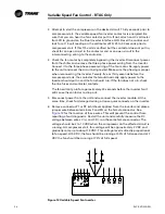
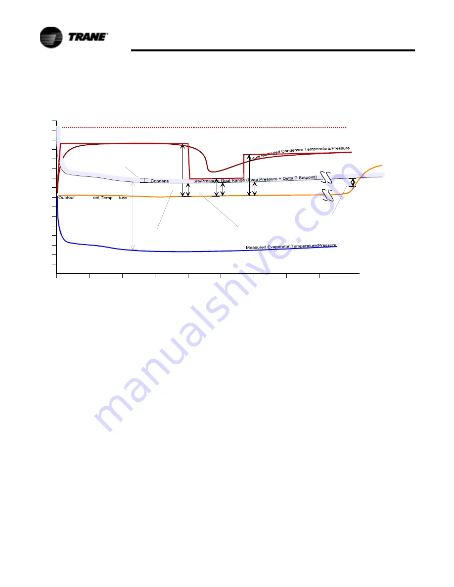
In normal fan control, a new % fan capacity will be calculated at each iteration per
the fan control algorithm. The algorithm attempts to control the fans so that the
condenser pressure is held to within a 4.5 F deadband above the condenser goal
pressure which is set relative to the current Evaporator Pressure (i.e. 60 PSID
above it).
If variable speed fans are present, then the air flow is modulated directly on the
Desired New % Air Flow calculated every 5 seconds.
When only fixed speed fans are present, additional fans will not be staged on
until the new % Air Flow exceeds the next available fan step.
Figure 11. Condenser Fan Control
150
140
130
120
110
100
90
80
70
60
50
40
30
20
10
0
T em perature
(
0
F)
D elta P
S etpoint
60 P sid
A
i
r Am bi
era
G D T = G oal D elta T
(G oal to O utdoor Air Tem p)
A D T
1
G D T
1
er Tem perat
As G D T approaches zero and goes negative,
new % airflow w ill be clam ped at 10x present airflow
R TA C C ondenser Fan C ontrol
A D T = A nticipated D elta T
(Asym ptote of C ondenser Tem p
relative to O utdoor A ir Tem p)
P anic Fan Add Line: If C ondenser P ressure/Tem perature rises above this line,
one additional fan w ill be added each 5 seconds itteration.
A D T
3
G DT
3
G D T
2
AD T
2
Predicted A sym ptote of C ondenser Tem perature/Pressure
0 5 10 15 20 25 30 35 40
4.5 F D eadband


