background image

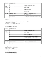
Command

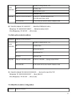
ID 46 07 00 (CRC)

Syntax

Description

ID

Address of setting module 1~247

46

Function Code

07

Read module’s Firmware 

00  

Reserved code

Response

ID 46 07

 YY


MM


DD 

00(CRC)

ID 46 07 ……Module command Line

YY

:Year

  MM 

:Month 

 DD:

Date  

00 : Reserved code

ID C6 00 (CRC)

ID C6 (CRC) C6:Function Code 00: Reserved code

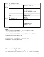
Example:

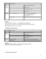
Send Command:”01 46 07 00”…….Set up TRP-C28’s configuration.
Response:”01 46 07 07 04 06 00“…APR. 04.2007 TRP-C28 Firmware Version.
Error Response: “01 C6 00”……Error code.

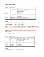
10-6.Read module reset status

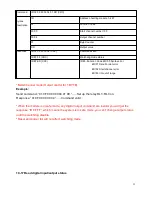
Command

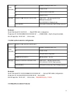
ID 46 08 00(CRC)

Syntax
Description

ID

Address of setting module 1~247

46

Function Code

08

Read Module Reset status

00 

Reserved code

Response

ID 46 08 0D 00 (CRC)

D=0 Have been read, D=1 Have been reset

ID C6 00 (CRC)

ID C6 (CRC) C6:Function Code 00: Reserved code

Example:

Send Command:”01 46 08 00”…Read the module’s digital input status.
Response:”01 46 08 1 00 ..have been reset.

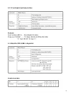
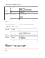
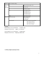
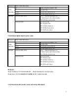
10-7.Set up the module reset 

26

Summary of Contents for TRP-C28

Page 1: ...rmation in this manual is subject to change without prior notice in order to improve reliability design and function and dosed not represent a commitment on the part of the manufacturer No part of thi...

Page 2: ...pports baud rates from 1 2Kbps to 115 2 Kbps All 4 channels digital input ca be used as counter Digital input signal with 3750Vrms isolation protection Dual watchdog Module s firmware host computer tr...

Page 3: ...xternal DC adapter Connection type Screw terminal accepts AWG 12 32 wires Power consumption 2 7W Operating environment 0 to 65C Storage temperature 20 to 65C Humidity 10 90 Non condensing Dimension 15...

Page 4: ...1 5 Pin Definitions 2 Communication Wiring 3 Wire Connection 4...

Page 5: ...ct protocol between Modbus RTU and ASCII The dip switch also provides back to default function when user forget the configuring information stored in EEPROM such as ID RS 485 Module address baud rate...

Page 6: ...odule reboot then into power on mode the module s digital output value will return to the before setting And module can accept the host s command to change the digital output value Dual Watchdog Modul...

Page 7: ...module into the safe mode the digital out will not be changed until the watchdog disable 6 TRPCOM Command Protocol Description Command Format Leading Code ID Address Command CHK cr Response Format Le...

Page 8: ...cr Read the module s name See 8 14 IDF CHK cr Read the module s firmware version See 8 15 ID5 CHK cr Read the module reset status See 8 16 IDONN CHK cr Change the module s name See 8 17 IDLEDA CHK cr...

Page 9: ...DD Data format See 8 3 CHK Checksum cr Carriage return Response ID CHK cr Command valid ID CHK cr Command Invalid 8 2 Baud rate setting BB 8 3 Data format setting DD Example Send command 0001400600 If...

Page 10: ...nd 010008 Data 08 DO0 DO3 0001 RL1 RL2 RL3 OFF RL4 ON Response Command valid Example Send command 01000G Data 0G Data error Response 01 Parameter error Single Channel mode Output control for one BIT E...

Page 11: ...alue to EEPROM by using the command IDCS The counter s value will reset to 0 if power fail or send command IDRS 8 6 Clear digital input N channel counter value Example Send command 01C2 Clear DI2 coun...

Page 12: ...must save new value in EEPROM again or the module will load old value if power fail or reset 8 8 Save all digital input counters value to EEPROM Example Send command 01CS Save DI0 DI3 counters value...

Page 13: ...nse of key stoke However the user will lost the stoke information because the key input is pulse digital input If user read by the command ID6 in time A and time B the response is that no key stoke Us...

Page 14: ...digital input output status Example Send command 016 Read digital I O status Response 01060C 6 Relay RL1 RL4 OFF RL2 RL3 ON C Input DI0 DI1 for logic 0 8 12 Read the TRP C28M configuration Data format...

Page 15: ...sing Checksum Enable Model 0 TRP C28M See Data format table 8 13 Reset the module status Example Send command 01RS Reset TRP C28M Response 01 Have been reset Reset will clear all digital output status...

Page 16: ...MMDD Mod The module type YY Year MM Month DD Date ID CHK cr Example Send command 01F Read the TRP C28M s version Response 01C28M070412 The TRP C28M s version date is 04 12 2007 8 16 Read the module re...

Page 17: ...the module s LED operating mode IDLEDA CHK cr Syntax description First Leading code ID Address of setting module 00 FF HEX A A 0 Turn on all LED when DIO enable off A 1 Turn off all LED when DIO enabl...

Page 18: ...e watchdog will re counted When the module is in safe mode any digital output command are invalid you will get the response IDWE which means the system is in safe mode you can t change output status R...

Page 19: ...D0F Command valid set the watchdog timeout is 0F 1 6 Sec 8 22 System stand by Host OK If watchdog is in enable send the Host Ok command before watchdog timeout B the watchdog will re count PWR LED wil...

Page 20: ...HK cr Command invalid Example Send Command 014S Read safe mode digital output status Response 01080F Command valid safe mode digital IO status is 080F 8 24 Save current digital output status to power...

Page 21: ...nt digital IO status All modules on line Then send command 014 Read synchronized data Response 1010E00 1 Have been send the the DIO status valid is 010E After Read synchronized data A value is 1 Read...

Page 22: ...e Format ID HEX FC HEX SU HEX DA HEX or RC HEX CRC16 HEX Error Format ID HEX FC HEX CRC16 HEX ID RS485 Device Address HEX 1 247 1Byte FC Function Code HEX 1 Byte SU Sub Function HEX 1 Byte DA Data For...

Page 23: ...Set up LED panel status 10 10 ID 46 27 DD 00 CRC Set up power on mode 10 11 ID 46 28 00 CRC Read power on mode value 10 12 ID 46 29 DD 00 CRC Set up safe mode value 10 13 ID 46 2A 00 CRC Read safe mo...

Page 24: ...r Response 01 C6 00 Error code 10 2 Set up the module s address Command ID 46 04 IP 00 00 00 CRC Syntax Description ID Address of setting module 1 247 46 Function Code 04 Set up module s ID IP New mod...

Page 25: ...e 01 C6 00 Error code 10 4 Set up the module s configuration Command ID 46 06 00 BD 00 00 00 00 00 00 CRC Syntax Description ID Address of setting module 1 247 46 Function Code 06 Set up module s conf...

Page 26: ...onfiguration Response 01 46 07 07 04 06 00 APR 04 2007 TRP C28 Firmware Version Error Response 01 C6 00 Error code 10 6 Read module reset status Command ID 46 08 00 CRC Syntax Description ID Address o...

Page 27: ...00 Error code 10 8 Set up watchdog timeout value or disable Command ID 46 0B WS 00 CRC Syntax Description ID Address of setting module 1 247 46 Function Code 0B Set up power on mode WS WS 00 Watchdog...

Page 28: ...ue Response 01 46 0C 01 0F Error Response 01 C6 00 Error code 10 10 Set up panel LED status Command ID 46 0D 0S 00 CRC Syntax Description ID Address of setting module 1 247 46 Function Code 0D Set Up...

Page 29: ...ror Response 01 C6 00 Error code 10 12 Read power on mode value Command ID 46 28 00 CRC Syntax Description ID Address of setting module 1 247 46 Function Code 28 Read power on value 00 Reserved code R...

Page 30: ...or Response 01 C6 00 Error code Power on mode Digital output states when watchdog timeout 10 14 Read safe mode value Command ID 46 2A 00 CRC Syntax Description ID Address of setting module 1 247 46 Fu...

Page 31: ...85 FF CRC Watchdog mode status ID 85 ER CRC ID 85 Error Code ER 00 Syntax error ER 01 Data Format error ER 02 Start channel error ER 03 I O out of range Single Channel mode Output control for 1 Bit E...

Page 32: ...ER 01 Data Format error ER 02 Start channel error ER 03 I O out of range Multi Channel mode Output control for 1 BYTE Example Send command 01 0F 00 00 00 04 01 0E Set up the relay RL1 RL3 on Response...

Page 33: ...mber Response ID 01 BC DD CRC ID 01 Command Line BC Byte counter DD DIO Status ID 81 ER CRC ID 81 Function Code ER 00 Syntax error ER 01 Data Format error ER 02 Start channel error ER 03 I O out of ra...

Page 34: ...mber Response ID 02 BC DD CRC ID 01 Command Line BC Byte counter DD DIO Status ID 82 ER CRC ID 82 Function Code ER 00 Syntax error ER 01 Data Format error ER 02 Start channel error ER 03 I O out of ra...

Page 35: ...digital input counter value Command ID 04 00 SS 00 NN CRC Syntax Description ID Address of setting module 1 247 04 Function Code 00 SS Start channel number SS 00 00 NN Channel number NN 01 04 Response...

Page 36: ...rror ER 02 Start channel error ER 03 I O out of range Example Send command 01 0F 02 00 00 04 01 00 Clear channel 0 3 counter value Response 01 0F 02 00 00 0F Command valid Send command 01 0F 03 00 00...

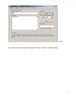
Page 37: ...to 115200 Checksum Enable or Disable See Figure 1 The Module Factory Setting is 9600 and ID is 01 Checksum is Disable Turn module s switch to OFF ON position into ASCII communication mode 2 The Termin...

Page 38: ...If you don t know the module s ID may select Scan to find the module s setting 38 Figure 2...

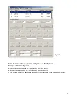
Page 39: ...nfiguration Example TRP C29 Configuration A Get Counter Value please click Digital Input D0 D7 button B Enable the digital output click Digital Output D0 D7 button C Set up new RS485 ID Baud Rate and...

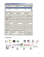
Page 40: ...12 Application 40...

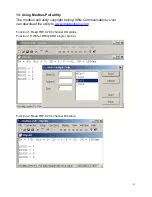
Page 41: ...poll utility copyright belong Witte Communications User can download the utility to www mosbustools com Function 1 Read TRP C28 4 channel DO status Function 15 Write TRP C28 DO single channel Functio...

Page 42: ...Function 3 4 Read TRP C28 CH0 3 Counter value Function 6 Write Channel 1 counter value Function 3 4 Read TRP C28 CH0 CH3 Counter value Function 16 Write Channel 0 3 counter value 42...

Reviews: