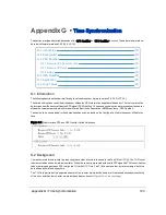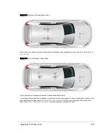
Figure G-2 Top of Hour Counters
The combined value represents the number of microseconds since the top of the hour. It ranges from 0 to 3,599,999,999
μs -- there are 3.6 × 10
9
μs in one hour. The sub-second counter range alone spans 0 to 999,999 μs.
The sensor continuously monitors the PPS input assessing the timing characteristics of any pulses presented. This pro-
cess is indicated both on the Web Interface (see
Configuration Screen on page 69
) and in the position packet. When the
sensor detects a valid, stable PPS signal, the Web Interface indicates “PPS: Locked” and the PPS status field in the pos-
ition packet at offset 0xF4 is set to 0x02.
As noted, the sensor counts microseconds using an internal oscillator. This internal oscillator always drives the sub-second
counter; however, the sensor may be configured to use a valid PPS signal to adjust the value of the sub-second counter
every second, thereby reflecting the "top of second" moment indicated by the rising edge of the PPS.
The minutes and seconds counter may be adjusted to the time values provided in the NMEA sentence. If no NMEA sen-
tence is provided, the minutes and seconds counter is incremented every second.
Using the PPS signal to adjust the sub-second counter allows the sensor to remain synchronized to a PPS source even if
that source is drifting slightly. This might occur when a GPS receiver indicates an invalid fix and begins using its own internal
time to drive the PPS reference.
New control options (PPS Qualifier and GPS Qualifier, described below) have been added to allow the user to finely adjust
the manner in which the sensor reacts when a valid PPS is confirmed and locked onto.
G.3 PPS Qualifier
The three settings described below (and in
Logic Tables on the facing page
) control how the sensor adjusts the TOH
counter based on GPS and PPS signal status.
Depending on the GPS receiver's valid/invalid status, the three settings determine if the sensor's Top-Of-The-Hour (TOH)
counter should enter free-running mode or synchronize the sub-second counter with the rising edge of the PPS signal.
G.3.1 Require GPS Receiver Valid
This setting determines the manner in which the sensor utilizes the current status of the GPS receiver provided in the
NMEA sentence.
If the Require GPS Receiver Valid is set to On, the sensor requires the GPS receiver to indicate a valid satellite
condition before using the rising edge of a PPS signal to adjust the internal sub-second counter.
Note: The sensor must also receive a valid NMEA message indicating the GPS receiver is providing a valid time stamp.
If Require GPS Receiver Valid is set to Off, the sensor synchronizes its sub-second counter to the rising edge of
the PPS signal regardless of GPS receiver satellite status.
G.3.2 Require PPS Lock
This setting determines the manner in which the sensor validates the PPS signal prior to adjusting the internal sub-second
counter to the rising edge of that PPS signal.
124
VLP-16 User Manual


