background image

2019/05/01 00:16

15/17

OEM Integration Guide

Product Manuals - http://www.vescent.com/manuals/

used by a connected system to determine whether it is safe to allow signalling on the USART lines. If a
level-shifter or isolator is to be used in the system, it is recommended to use this 3.3V rail to power
the side connected to the master controller to prevent any signalling to go through to the master
controller when it is unpowered.

If no level-shifting or isolation is desired, then it is
recommended for the OEM integrator to use 1kΩ series
resistors on all USART communication lines going into the
master controller. These series resistors will protect the
microcontroller from over-voltages up to 3.3V while it is
unpowered.

USB to Serial Conversion

For ease of communication from a PC, it may be desirable to use a USART to USB converter. A
commonly used IC to do this is an 

FTDI 232RL

. This FTDI chip connects to the 3.3V UART interface and

then creates a virtual COM port on the PC connected to it. Standard methods of interacting with serial
ports may then be used for sending commands to the ICE-MC1 master controller. The FTDI chip has
an onboard 3.3V regulator and can be configured to signal at 3.3V on the serial UART lines. In
accordance with the UART protection recommendations given above, the 3.3V power rail provided
from the master controller can be used to power the FTDI chip's UART signalling pins, thereby
preventing any damage from occurring by signalling into an unpowered microcontroller on the master
controller. If this technique isn't used, series resistors should be used on the UART lines.

Sometimes the PC communicating with the ICE modules may be located far away or on a different
power circuit in the building. In this case, it may be desirable to isolate the power and ground of the
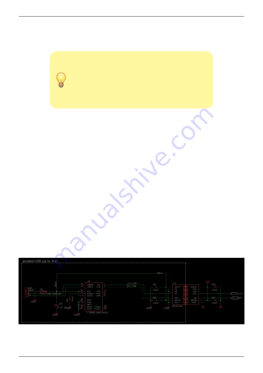
PC (via the USB cable) by using an galvanic isolator. The easiest place to put this isolator is between
the FTDI chip and UART of the master controller. The master controller's 3.3V rail can be used to
power one side of the isolator and the USB 5V rail can be used to power the other. The 

ICE Platform

enclosure

 uses an 

Analog Devices ADUM7441

 to do this. An example implementation of this is shown

in 

figure 15

.

Fig. 15: Example implementation of USB isolation using ADUM7441

Summary of Contents for ICE

Page 1: ... tabs Once the boards are stacked together each board can be addressed and communicated with through a serial I 2 C bus see this page for I 2 C details Each daughter board can have a specific I 2 C address set via dip switches on each circuit board and the master controller ICE MC1 can route commands directly to each board The master controller also routes and manages the power bus going to each bo...

Page 2: ...rator s system are also detailed in the document Can t find what you are looking for A forum has been established for Q A and information dissemination We invite you to join Power Requirements Power Entry Power needs to be supplied to the power bus headers on all ICE circuit boards These headers and respective supply voltages are shown in figure 3 The ICE master controller board ICE MC1 takes a sing...

Page 3: ...pable of carrying the maximum current of the 5V_A line Since the master controller handles all power sequencing requirements the power connections for 5V_A 15V and 15V can be applied in any order so long as both ground connections have been established The master controller will not turn on if any of the required voltages are not present or are out of range These power entry inputs are also revers...

Page 4: ...turning on and off each voltage rail must be followed as described in the power sequencing section or damage will occur Power Draw by Module The power supply capacity for the supply used to power the ICE stack must be sized appropriately to handle expected power draw for the modules selected Current draw is listed in the specifications for each of the daughter modules The typical values indicate the...

Page 5: ...ributes power to all daughter modules must have each voltage rail properly sequenced when turning power on and off The ICE MC1 master controller automatically takes care of this power sequencing to protect daughter modules If power is being applied directly to the power bus by the OEM integrator the power sequencing outlined in this section must strictly be followed to prevent damage to the daughte...

Page 6: ...and shutdown the ICE stack There is a 4 pin Molex connector Molex PN 22 05 3041 which allows for connection to a OFF Mom style normally off momentary on push switch and power for an LED to indicate power state The pin diagram is shown in figure 3 labeled as Power Switch For reference the pin definition is shown in table 1 Pin Name Function 1 Switch Connect to one terminal of push switch 2 GND_D Conne...

Page 7: ...tch must be toggled once to turn on power This behavior can be changed at the factory If no push switch is desired the momentary switch can be replaced with a MOSFET controlled by another part of the OEM system Mechanics Mounting The ICE stack needs to be mounted to a grounded chassis Each ICE circuit board has mounting holes located in each corner for 4 40 thread standoffs Please see the PCB Mecha...

Page 8: ...anical Specifications page for more details and technical drawings Each PCB exposes up to 4 copper tabs to conduct heat out from power dissipating components to an external heat sink The copper tabs are not electrically isolated so electrical isolation is required at the interface between the heatsink and copper tab Failure to isolate these tabs will result in malfunction of the ICE module For elec...

Page 9: ...ach ICE daughter module exposes analog interfaces on the side opposite to the copper heatsink tabs Each module s circuit board may use a mixture of the connectors described in this section Each connector and an associated part number shown below such that the OEM integrator my chose a suitable mating connector for their system Consult the product pages for each ICE module to determine the type pos...

Page 10: ...e copper heatsinking tabs will be on the opposite side The master controller ICE MC1 also follows this convention with the exception being the serial port flat flex connector Ultra Miniature Coax Connector UMCC The surface mount UMCC connectors Molex PN 0734120110 are used on the ICE CS1 and ICE CP1 for handling low frequency analog signals 8 GHz A UMCC to UMCC cable or UMCC to SMA cable may be used...

Page 11: ...n FFC connector on the other end The ICE system uses right angle 1 00 mm pitch bottom contact FFC connectors Generally the minimum bend radius for flat flex jumper cables is 2mm The length of the stiffener behind the exposed contacts on the cable will determine how far out from the FFC pcb connector the first bend of the flat flex cable can occur The clearance for this bend must be accounted for when de...

Page 12: ...manuals Printed on 2019 05 01 00 16 Fig 10 Surface mount 12 pin 1 00 mm pitch bottom contact FFC connector FCI PN SFW12R 1STE1LF Fig 11 FFC jumper cable 12 pin 1 00 mm pitch Molex PN 0210390269 SMA Connector These board edge SMA connectors Emerson PN 142 0701 881 are used on the ICE CP1 for handling high frequency RF signals 8 GHz ...

Page 13: ... not including the ICE MC1 master controller can be stacked together Each ICE circuit board has a 3 position DIP switch shown in figure 13 installed that allows the setting of each modules I 2 C address between 0 7 The selection of address is in binary with DIP position 1 corresponding to the least significant bit Setting a bit HIGH is done by sliding the switch to the side marked with the word ON w...

Page 14: ...g levels Inputting 5V TTL signals will damage the circuit board When the master controller is in an off state either from having been shutdown by the power switch or has just had power applied to its input but hasn t had the power switch pressed yet no voltages should be applied to UART Since the UART idles in a HIGH state usually a serial device connected to a shutdown master controller could pote...

Page 15: ...serial ports may then be used for sending commands to the ICE MC1 master controller The FTDI chip has an onboard 3 3V regulator and can be configured to signal at 3 3V on the serial UART lines In accordance with the UART protection recommendations given above the 3 3V power rail provided from the master controller can be used to power the FTDI chip s UART signalling pins thereby preventing any dama...

Page 16: ...ning off any voltage rails for shutdown the System Shutdown Read I 2 C command should be sent to the stack The ID of this command is 3 and takes no arguments To send the command send an I 2 C packet on one byte with the value of 0x03 to each ICE daughter module address possible addresses are 0 7 This packet should be sent at least 1 second before turning off any power rails to give time for all ICE ...

Page 17: ...7 OEM Integration Guide Product Manuals http www vescent com manuals From http www vescent com manuals Product Manuals Permanent link http www vescent com manuals doku php id ice oem_integration Last update 2014 07 30 18 37 ...

Reviews: