www.vtiinstruments.com
SMP7500 Programming
47
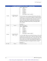
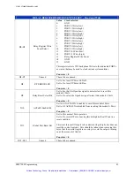
The PORT Inn/Out Select bit controls the direction of the Port. Set to 0, it sets the Port’s direction
as an input. This allows the module to receive (read) the port lines when properly clocked. This bit
set to 0 may be overridden by the F/P GND_I/O line, so care should be taken when setting up this
example.
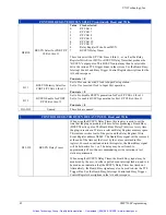
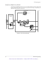
Once the PORT is configured as an input port, a clock source for the input register must be
selected. By setting the PORT Clock to Input Port Select Bits, the source of the clocking signal to
the input register is selected. In this example the bits are set to 2 to allow the Relay Register
000Ch Write Event to clock the data from the UUT into the input PORT. (Note also that the F/P
CLK line out to the UUT might also be selected as the input clock for this PORT since it is the
F/P CLK line that will also be clocking data out of the UUT.) By setting the PORT Clock to Input
Port Polarity Bit, either positive or negative edge operation of the clock to port data input may be
controlled. This bit is set to 1 for inverted, or negative edge, operation of the PORT Clock to Input
Port Signal in this example. Data will be latched on the falling edge (second edge) of the Relay
Register Write Event. And finally, the input port must be set to synchronous, or asynchronous
operation. Setting the PORT Input Clock Select to 1 sets the input port to latch data on occurrence
of the PORT Clock to Input Port edge that is selected. This example sets this bit to a 1.
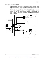
To setup the PORT’s clock signal as an output, the signal that will produce the PORT Output
Clock must be selected by setting the PORT Output Clock Select Bits. In this case, the PORT
Output Clock Select Bits are set to 2 to select the Relay Register write Event. The PORT Output
Clock Polarity Select Bit should then be set for positive edge sensitivity. This bit is set to 0 in this
example. The UUT will be clocked on the rising edge (first edge) of the Relay Register Write
Event. The PORT Output Clock Enable Bit must then be set to 1 to enable the Output Clock to
drive the F/P CLK line.
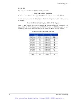
To achieve the state of the Port as described above, the following must be written to a PORT’s
Control Register.
Write = h3A80 to the PORT’s Control Register
This concludes the programming of the bits that are necessary to configure a PORT as an input
port with inverted Clock to Input Port operation, and to set that PORT’s F/P CLK pin as an
output. Note that other bits in the control register might also be set to affect other control
functions of the Port selected.
Since the PORT has been configured as in input port, no data must be loaded into the I/O Register
Buffer.
The PORT of interest is now ready to receive data from the UUT. It will latch data on the falling
edge of the F/P CLK.
When the Relay Register Write Event is initiated, the F/P CLK signal is transmitted to the UUT. It
is assumed that subsequently the data on the UUT’s outputs are now available to the Input Port.
After the duration of the Relay Register Write Event, the falling edge of the event will clock data
into the Input Port. By utilizing the BUZYN Signal feature an indication to the host controller can
be configured to occur when the falling edge of the Relay Register Write Event signal is received.
The SMP7500 module initiates an event on a selected TTL Trigger line that may be used to
inform the slot 0 controller that the transfer has occurred and that data may then be read from the
PORT.
Artisan Technology Group - Quality Instrumentation ... Guaranteed | (888) 88-SOURCE | www.artisantg.com


