34
Virtex-6 FPGA System Monitor
UG370 (v1.1) June 14, 2010
System Monitor Timing
over to an internal clock oscillator to continue monitoring. This is similar to the mode of
operation pre-configuration (see
Pre-Configuration Operation, page 10
). After
configuration, the DCLK input requires 20 DCLKs to resynchronize to the external clock. It
will not be possible to access the DRP until resynchronization has occured.
Continuous Sampling
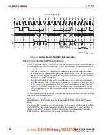
In continuous-sampling mode, the ADC continues to carry out a conversion on the
selected analog inputs.
shows the timing associated with continuous-sampling
mode. The ADCCLK is generated by a clock divider (see
). The analog-to-digital conversion process is divided into two parts, the
acquisition phase and the conversion phase.
Acquisition Phase
During the acquisition phase, the ADC acquires the voltage on a selected channel to
perform the conversion. The acquisition phase involves charging a capacitor in the ADC to
the voltage on the selected channel. The time required to charge this capacitor depends on
the selected input-channel source impedance. The acquisition time is nominally four
ADCCLKs in duration, from the end of the previous conversion phase to the sampling
edge of the next conversion phase (see
When operating in Single Channel mode, the user must write to configuration 0 to select
the next channel for conversion. Write operations to the configuration registers to select the
next channel should occur before the end of the current conversion (EOC pulse). In
sequencer mode, this channel selection is automatically made (see
).
If the ACQ bit in configuration register 0 is set to logic 1, then an extra six ADCCLK cycles
are inserted before the sampling edge (in Single Channel mode) to allow for more
acquisition time on a selected channel. This is useful if an external channel has a large
source impedance (greater than 10 k
Ω
). The extra ADCCLKs are shown in
the additional clock cycles numbered in red. To extend the acquisition time when using the
channel sequencer, the desired bits in registers
4Eh
and
4F
must be set High (see
).
For more information on the effects of source impedance on the acquisition, see
, ADCCLK is an internal clock used by the ADC.
www.BDTIC.com/XILINX


