10
Virtex-6 FPGA System Monitor
UG370 (v1.1) June 14, 2010
Pre-Configuration Operation
User Attributes
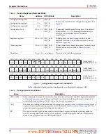
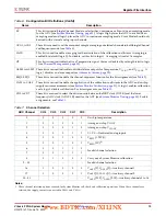
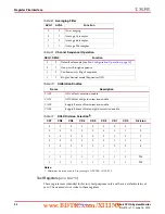
System Monitor functionality is configured by the Control registers (see
). These Control registers can be initialized at design, using the Attributes
listed in
and through the DRP at run time (see
Pre-Configuration Operation
System Monitor starts operating in a
safe mode
of operation shortly after the FPGA is
powered-up without performing a configuration.
Note:
Holding INIT_B or PROG Low to delay configuration has no effect on System Monitor. System
Monitor is available as soon as the Clear Configuration Memory step is complete, which is normally
indicated by INIT_B going High. See the “Configuration Sequence” section in the
Virtex-6 FPGA
Configuration Guide
for more information.
In this mode of operation, System Monitor operates in a sequence mode (see
), monitoring the on-chip sensors: temperature, V
CCINT
, and V
CCAUX
.
When operating in safe mode, System Monitor is not affected by any change in the FPGA’s
configuration. System Monitor operates in safe mode prior to any configuration and
during configuration (full and partial). It is possible to customize the System Monitor
operation pre-configuration using the JTAG TAP. However, System Monitor only operates
in safe mode during configuration and the contents of the System Monitor control registers
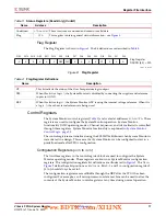
JTAGLOCKED
(1)
Output
Used to indicate that a DRP port lock request has been made by the Joint Test Action
Group (JTAG) interface (see
JTAGMODIFIED
(1)
Output
Used to indicate that a JTAG Write to the DRP has occurred.
JTAGBUSY
(1)
Output
Used to indicate that a JTAG DRP transaction is in progress.
Notes:
1. Active-High signal.
2. For some details on the timing for these DRP signals, consult
and
Reconfiguration Port) in the
Virtex-6 FPGA Configuration Guide
.
3. Rising edge triggered signal.
Table 1:
System Monitor I/O
(Cont’d)
Port
I/O
Description
Table 2:
System Monitor Attributes
Attribute
Name
Control
Register
Address
Description
INIT_40
Configuration register 0
40h
System Monitor configuration registers (see
INIT_41
Configuration register 1
41h
INIT_42
Configuration register 2
42h
INIT_43 to
INIT_47
Test registers
43h
to
47h
System Monitor Test registers for factory use only. The default
initialization is
0000h
.
INIT_48 to
INIT_4F
Sequence registers
48h
to
4Fh
Sequence registers used to program the Channel Sequencer
function in System Monitor (see
).
INIT_50 to
INIT_57
Alarm Limit registers
50h
to
57h
Alarm threshold registers for the System Monitor alarm function
(see
www.BDTIC.com/XILINX


