background image

35

DarkStar User Guide

 3:  Software

www.xkl.com

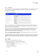
localhost CONF# 

line console

localhost CONF-LINE-CTY# 

login

localhost CONF-LINE-CTY# 

end

localhost# 

write memory

Are you sure? [yes/no] 

yes

localhost#

NOTE

If you set a single-login password for CTY or VTY access, it will remain in the configuration file, but 
will not remain in effect. The single-login password is not required while user accounts are active. 
However, if you then revert to single-login password again, gaining access will still require the single-
login password you originally assigned. If login local is set, only the username/password pairs may 
be used at that time.

WARNING

!

If the customer (startup) flash becomes unreadable for any reason, the DarkStar system 
enters recovery mode and reverts to factory settings, in which case Telnet access is 
disabled and only the console can be used for diagnosis and repair. 

3.2.10.3     Access Control Lists

ACLs (Access Control Lists) may be used to enhance security and mitigate opportunities for denial-of-service attacks. This 
feature is particularly important if the DarkStar system is not on a private management network and/or remote Telnet/SSH 
access is enabled.

Incoming router traffic is compared to ACL entries based on the order that the entries occur in the router. The router searches 
for matches and denies traffic if no match is found. There is an implied denial for traffic that is not permitted. A single-entry 
ACL with only one deny entry has the effect of denying all traffic. New statements are automatically added to the end of the 
list. Therefore, it may be helpful to place frequently used entries at the top of the list. 

IP ACLs use masks with IP addresses to specify permission or denial. Masks used to configure IP addresses begin with 255 and 
place larger values on the left side. For example, a typical IP address such as 209.165.202.129 uses a mask of 255.255.255.224. 
However, masks for IP ACLs are complemented, and in this case the mask would be 0.0.0.31. This usage is sometimes referred 
to as an inverse or wildcard mask. When the value of the mask is broken down into binary, the results determine which address 
bits are considered to process traffic. “0” indicates that the address bits must be considered (exact match); “1” indicates no 
match and no consideration is made. 

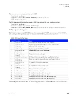
The following example illustrates how to enable an ACL and applies to connections on the VTY:

localhost> 

enable

localhost# 

configure

localhost CONF# 

access-list 2 permit 10.0.0.0 0.255.255.255

localhost CONF# 

access-list 2 deny 0 255.255.255.255

localhost CONF# 

line vty

localhost CONF-LINE-VTY# 

access-class 2 in

localhost CONF-LINE-VTY# 

exit

Summary of Contents for DarkStar DBA-L

Page 1: ...DarkStar Lightingthepathtonetworkindependence UserGuidev3 1 ...

Page 2: ... U S Government is subject to the restrictions described in FAR 48 CFR 52 227 14 or DFARS 48 CFR 252 227 7014 as applicable Technical Data acquired by or for the U S Government if any is provided with Limited Rights Use duplication or disclosure by the U S Government is subject to the restrictions described in FAR 48 CFR 52 227 14 or DFARS 48 CFR 252 227 7013 as applicable Class A Compliance DarkS...

Page 3: ... cryptsoft com The SSLeay library is free for commercial and non commercial use as long as the following conditions are adhered to The following conditions apply to all code found in this distribution be it the RC4 RSA lhash DES etc code not just the SSL code Redistribution and use in source and binary forms with or without modification are permitted provided that the following conditions are met ...

Page 4: ...m this software may not be called OpenSSL nor may OpenSSL appear in their names without prior written permission of the OpenSSL Project 6 Redistributions of any form whatsoever must retain the following acknowledgment This product includes software developed by the OpenSSL Project for use in the OpenSSL Toolkit http www openssl org NetBSD Foundation DarkStar technology contains code derived from s...

Page 5: ...st of conditions and the following disclaimer in the documentation and or other materials provided with the distribution THIS SOFTWARE IS PROVIDED BY THE AUTHOR AND CONTRIBUTORS AS IS AND ANY EXPRESS OR IMPLIED WARRANTIES INCLUDING BUT NOT LIMITED TO THE IMPLIED WARRANTIES OF MERCHANTABILITY AND FITNESS FOR A PARTICULAR PURPOSE ARE DISCLAIMED IN NO EVENT SHALL THE AUTHOR OR CONTRIBUTORS BE LIABLE ...

Page 6: ... Enterprises Inc makes no representations about the suitability of this software for any purpose It is provided as is without express or implied warranty University of Michigan Merit Network Copyright 1992 1993 1994 1995 The Regents of the University of Michigan and Merit Network Inc All rights reserved Permission to use copy modify and distribute this software and its documentation for any purpos...

Page 7: ...granted to make and use derivative works provided that such works are identified as derived from the RSA Data Security Inc MD5 Message Digest Algorithm in all material mentioning or referencing the derived work RSA Data Security Inc makes no representations concerning either the merchantability of this software or the suitability of this software for any particular purpose It is provided as is wit...

Page 8: ...on Systems DBA L DRA 3 DBA L Systems 4 DRA Systems 4 Band Combiner Devices DBC 5 Key Benefits 6 Network System 6 Hardware 6 Software 6 2 Hardware 9 Power 9 Power Requirements 9 AC Power 9 DC Power 9 DarkStar DC Power Connection Matrix 10 Power Module Replacement 11 Fan Modules 12 Fan Module Replacement 12 Optical Configuration 13 Optical Modules 13 Wave Laser Module 13 Client Laser Module 13 OSC L...

Page 9: ...24 Redundancy APP 24 Administrative Access 27 Console Serial Interface 27 Telnet Access 28 Console Jack Pinout Configuration 28 SSH Access 29 SSH Key Replacement 29 Loopbacks 30 Management Network Services 30 Time and Date 31 Remote File Configuration 31 Security 33 Enabled Mode Password 33 Serial Console Password 34 Access Control Lists 35 Multiple Users 36 AAA with RADIUS and TACACS 36 Amplifier...

Page 10: ... 54 Create a saved configuration for backup 54 Getting operational again quickly 54 Automatic recovery from a warm restart 55 Automatic recovery from a cold boot or power recycle 55 Manual crash recovery only if automatic recovery fails 55 Diagnosis 55 Console Procedures 55 System Issues 56 System Troubleshooting Matrix 56 Networking Issues 57 Networking Troubleshooting Matrix 57 Hardware Procedur...

Page 11: ...x www xkl com CHAPTERS ...

Page 12: ...mmand line interface with router like operation that will be familiar to any enterprise network administrator 1 1 1 Network A DarkStar network consists of at least two Darkstar optical networking systems acting as endpoints Additional DarkStar networking systems DarkStar amplifier systems or DarkStar combiner systems can be added to enable extended network designs and enhance transport performance...

Page 13: ...e calculated using site installation metrics to determine the optical power required in a system It is often assumed that the more optical power a system offers the better it will perform In the world of optical networking too much optical power can cause just as many problems with signal quality as too little Therefore it is important that optical networking equipment be designed to operate withi...

Page 14: ...mplification systems share much of the same hardware and software as other DarkStar products requiring only one set of general operating instructions and commands to manage DarkStar products efficiently Beyond standalone amplifiers some amplification technologies may be directly integrated into optical networking systems DarkStar networks and systems currently support two types of amplification 1 ...

Page 15: ... is amplified WARNING EDFAscanproducehigh energysignalsthatposearisktohumaneyesight Furthermore an improperly configured EDFA can damage optical receivers both within the EDFA equipped DarkStar systems and in remote systems connected to the EDFA equipped system 1 3 2 2 DRA Systems A DRA system employs EDFAs and Raman amplifiers to implement optical amplification allowing for increased distances be...

Page 16: ...ssive device FIGURE 1 3 DarkStar Band Combiner Devices 9 5 3 4 65 63 9 7 9 62 36 367 6 7 9 9 4 5 05 05 05 6 05 6 05 9 4 5 Console Port Alarm LED s Line Port LED s Ethernet Management Ports East West Line Input Ports Reset Button Amp Status LED s East West Mid Stage Access Ports Line Output Monitor Ports East West Output Monitor Output Monitor DRA Console Port Alarm LED s Line Port LED s East West ...

Page 17: ... in a DarkStar network may provide total transmission distances of up to 2000km 1 4 2 Hardware DarkStar hardware features include Low Power Consumption Every system in the DarkStar family is rated at 64 125W typical Rackspace Efficiency Each system in the DarkStar family occupies only 1U of space in a standard equipment rack Comparable equipment from other manufacturers often occupies 8U of space ...

Page 18: ... can be hosted on a remote server to automate configuration of DarkStar systems Employ this feature to recover system settings upon reboot or to automatically provision multiple systems Management Network Services The management network can be used to integrate network services with your system including Simple Network Time Protocol SNTP Syslog RADIUS and Simple Network Management Protocol SNMP tr...

Page 19: ... same for all systems Power supply modules use either AC or DC power 2 1 1 Power Requirements For maximum availability DarkStar systems should be connected to two power circuits The circuits may be AC DC or a combination of AC and DC power The following power combinations are supported Two 100 240VAC Two 48VDC One 100 240VAC and one 48VDC 2 1 2 AC Power DarkStar products with AC power require no s...

Page 20: ...be used to complete wiring The table details wiring specifications for both 48V and 48V rails WARNING When connecting wires to the Input Terminal the ground connector GND must be connected first and disconnected last TABLE 2 1 DarkStar DC Power Connection Matrix Reference 48V Rail 48V Rail 48V 48V RTN GND GND 48V RTN 48V INPUT CONNECTOR INPUT TERMINAL ò ...

Page 21: ...ith care and re secure the bail after re inserting the power cord FIGURE 2 2 Replacing Power Supply Modules ò IF DC POWER latch 1 2 3 4 Click 5 6 Unplug the power cord from the power supply module Disengage the latch that secures the module in the chassis 1 2 Pull the module out of the chassis Insert the replacement module in the chassis 3 4 Snap the latch into place to secure the module You may n...

Page 22: ... when securing screws Fans are spinning 6 Fan Controller 0 Fan Controller 2 Unit 0 Unit 1 2 Caution fans are spinning 2 1 Locate the fan module in question The show environment fan command describes the physical location of each module and fan Using a Phillips head screwdriver remove the 4 screws that hold the module in place 3 4 Grasp the module by its handle and pull it out of the chassis Reinse...

Page 23: ...Laser Module The OSC laser module is located beneath the top access panel of the DarkStar system chassis 2 3 2 Optical Provisioning Optical interfaces are software configurable You use the DXMOS interface command to configure each wave and client interface and to assign a wave interface to each client interface Connections must be established physically first and then configured in DXMOS as detail...

Page 24: ...ry DRA system to properly clean the E2000 connector prior to instal lation FIGURE 2 4 Replace Laser Module Don tbendseverely 1 2 3 Slide the system forward on its rails far enough to access the panel Do not strain the attached fiber connections when sliding the system forward Fiber bends should not be smaller than 2 5 in diameter Using a Phillips head screwdriver unscrew the nine or five screws se...

Page 25: ...ge Tx Rx _ show interfaces Important 7 8 9 Insert the replacement laser module into the cage It will click when properly seated It may be helpful to compare its alignment with adjacent lasers to verify correct installation 8 7 Clean the fiber ends with an approved fiber cleaner a fiber cleaner is included with the DXM In a single step for each connector clean the fiber and insert it in the laser m...

Page 26: ...Close the hatch by sliding the access panel back to its original position Secure it by tightening the screws with a Phillips head screwdriver Only a quarter turn is required to fasten each screw 11 Slide the system into the rack and secure thumbscrews 10 ...

Page 27: ... Conventions for DXMOS Syntax Format Meaning localhost All text appearing on the command line is represented by Courier Standard font show interfaces User entries are represented by Courier Standard boldfaced font interface number Arguments such as free from input text number etc that the user replaces with variable information are represented by Courier Standard italicized font interface identifi...

Page 28: ... line CTRL N Scroll forward through the command history CTRL P Scroll backward through the command history CTRL R Redraw the current command input useful for restoring what was typed if the system writes output to the console while you enter a command CTRL U Clear the current command line contents and provide a new command prompt CTRL V Disregard any special meaning of the character following The ...

Page 29: ... IPv6 working IPv6 addresses are assigned using IPv6 Stateless Address Autoconfiguration see RFC 2462 This requires that there be at least one IPv6 router accessible on the local link The router should be configured so that the router adver tisement has the O flag set and the M flag cleared The prefix information option in the router advertisement should have both the L and A flags set The side re...

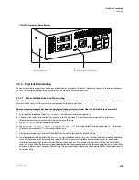
Page 30: ...fic To reset the software only Press and immediately release the front reset button Software reset maintains power and the state of customer traffic if the running configuration is identical to the startup configuration To warm reboot without a power cycle Press and hold the front reset button for three seconds Refer to the figure Hardware Reset Buttons on page 22 to locate the front reset button ...

Page 31: ...ts that trigger boot and recovery scenarios and their effects on the DarkStar system Please note that in the above table Push and release means pushing the button and immediately releasing it Push and hold means pushing the button and holding it in for at least 3 seconds There are two hardware reset buttons on DarkStar systems illustrated in Figure 3 1 on page 22 Pressing the side reset button alw...

Page 32: ...egy requires otherwise 3 Type configure to enter configuration mode 4 Type connect client x wave y encapsulation z x is the client interface to be connected y is the wave channel to be connected z is the encapsulation type 5 Connect to the remote DarkStar network on the other end of the fiber line and using the same process connect the same previously specified wave and client interfaces that term...

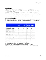
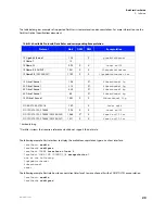
Page 33: ...connect client interface 0 to wave channel 0 with a SONET OC192 encapsulation localhost enable localhost configure TABLE 3 4 Available Protocols Data Rates and corresponding Encapsulation Protocol Gb s DXM DSM Encapsulation 1X Gigabit Ethernet 1 25 X gigabitethernet 10Gbase T 10 10Gbase W 9 95 X X Sonet oc192 10Gbase R LAN PHY 10 31 X X 10gigabitethernet 10GbaseR R FEC 255 237 11 09 X X 10gigabite...

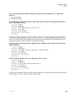
Page 34: ...milarly localhost enable localhost configure localhost CONF interface ethernet 0 localhost CONF INT ETH 0 ip address 192 168 0 1 24 localhost CONF INT ETH 0 end localhost write memory Are you sure yes no yes After Ethernet configuration is completed the DarkStar system can be integrated into your management network See the DarkStar DXMOS Command Reference for additional management network configur...

Page 35: ...3 Software www xkl com working interface must be accomplished manually This configuration may be desired because switching between currently selected resources incurs a brief disruption to the link measurable in milliseconds ...

Page 36: ...rmance In such a case it may be useful to set a holdoff value which specifies the time duration before an APP group reverts from the working to the protection interface Holdoff time is specified in milliseconds The following example illustrates how to set a holdoff value for an APP group in this case with a value of 1 minute 60000 milliseconds localhost enable localhost configure localhost CONF ap...

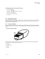
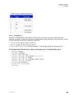
Page 37: ...d it is also possible to administer the system from a remote virtual VTY terminal using telnet or SSH Secure Shell 3 2 5 1 Console Serial Interface The console serial port is a minimal RS 232 Data Terminal Equipment DTE configuration Wiring for the 8 pin modular jack RJ 45 that connects the RS 232 connector to the console is illustrated below A console cable is provided with all DarkStar systems F...

Page 38: ...te login over VTY The transport input telnet command configures VTY to accept login attempts via the telnet protocol The following example illustrates how to configure remote telnet access to all configured Ethernet ports localhost enable localhost configure localhost CONF line vty localhost CONF LINE VTY password new password localhost CONF LINE VTY login localhost CONF LINE VTY transport input t...

Page 39: ...lient will ask the console operator to confirm the SSH access request subsequent SSH console access requests authenticate silently 3 2 5 4 SSH Key Replacement A DarkStar system ships with SSH keys already in place To replace the DarkStar SSH keys you must generate new SSH keys and transfer them to the DarkStar system The new SSH keys become activated at the next reload of DXMOS A DarkStar system s...

Page 40: ...exists is used as the source address for outbound IP messages instead of the IP address of the physical interface However if the Loopback Address is unconfigured the IP address of the physical interface is used DarkStar systems respond to inbound traffic using the destination IP which may be a physical interface address or the Loopback Address as determined by the sender Because a Loopback Address...

Page 41: ...UTC 7 Mon Mar 30 2009 If you run an SNTP server on a network reachable by the DarkStar system the command sntp server hostname will enable the clock to be set from the SNTP server 3 2 9 Remote File Configuration Once the management network is provisioned DarkStar systems are capable of remotely acquiring a configuration file via DHCP and TFTP for semi automated configuration This method of configu...

Page 42: ...dcast In this scenario you may use any active interface s client identifier or source MAC address in the corresponding DHCP server configuration file Be aware however that if the Ethernet interface or MAC address that you designate in the file is unable to reach the DHCP server no DHCP offer can be made and the configu ration process will fail The following example illustrates a portion of the req...

Page 43: ... DarkStar system s settings An enabled mode password will prompt for a password when the enable command is used The following example illustrates how to assign a password for enabled mode Assigning a password will override any previously set password localhost enable localhost configure localhost CONF enable secret password localhost CONF exit localhost write memory Are you sure yes no yes localho...

Page 44: ...ure localhost CONF line console localhost CONF LINE CTY no password localhost CONF LINE CTY end localhost write memory Are you sure yes no yes The following example illustrates how to create CTY user accounts localhost enable localhost configure localhost CONF user username password new password localhost CONF user another user password another password localhost CONF line console localhost CONF L...

Page 45: ... based on the order that the entries occur in the router The router searches for matches and denies traffic if no match is found There is an implied denial for traffic that is not permitted A single entry ACL with only one deny entry has the effect of denying all traffic New statements are automatically added to the end of the list Therefore it may be helpful to place frequently used entries at th...

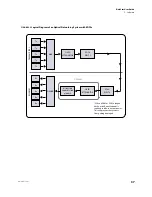
Page 46: ...d authenti cation authorization and accounting services The use of AAA services also allows more precision and control when using local login methods The TACACS protocol uses TCP and is not compatible with the earlier TACACS protocol that uses UDP as a transport 3 2 11 Amplifier Configuration DarkStar systems support two types of amplification EDFA and Raman Chapter 1 provides an overview of these...

Page 47: ...EDFAs When a DXM or DSM is looped back on itself an attenuator is required to reduce output power This will prevent the receivers from getting damaged OPTIONAL Tx Tx Tx Tx Tx MUX FIXED ATTENUATOR EDFA WEST 1 Rx Rx Rx Rx Rx DEMUX FIXED ATTENUATOR EDFA WEST 0 TRANSMITTERS RECEIVERS DISPERSION COMPENSATION MODULE ...

Page 48: ...m NO SHUTDOWN DO SHOW INTERFACE SUMMARY CONTROL OUTPUT POWER 5 0 DXM 5R CONTROL OUTPUT POWER 2 0 DXM 10 WAVE LASER RECEIVE POWER BETWEEN 14 AND 18 SHUTDOWN END WRITE MEMORY NO YES NO YES EDFA WEST 1 BOOSTER AMPLIFIER DO SHOW EDFA WEST 1 POWER INPUT 2dBm CONTROL OUTPUT GAIN 22 0 REPORTED OUTPUT POWER 19dBm END WRITE MEMORY SHUTDOWN CHECK TRANSMITTED POWER OF XFP TARGET VALUE 1 XFP 3 NO SHUTDOWN DO ...

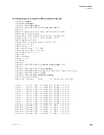
Page 49: ...CONF EDFA WEST 0 Amplifier edfa west 0 amplification up localhost CONF EDFA WEST 0 exit localhost CONF do show interfaces summary Switch Interfaces Summary Admin Line Rate kHz RxPow Ch Alarms Last Line Chng Client 0 Up LOS 10GE 40 0 dBm N A Nt_Rdy 0 01 18 40 Client 1 Up LOS 10GE 40 0 dBm N A Nt_Rdy 0 01 18 40 Client 2 Up LOS 10GE 40 0 dBm N A Nt_Rdy 0 01 18 40 Client 3 Up LOS 10GE 40 0 dBm N A Nt_...

Page 50: ... 2 Up Down 10GE 18 0 dBm 52 None 0 01 18 40 Wave West 1 Up Down 10GE 17 2 dBm 51 None 0 01 18 40 Wave West 0 Up Down 10GE 18 1 dBm 50 None 0 01 18 40 Admin Line Type IP Address Loopback 0 Up Up Loopback 172 30 127 227 32 OSC 1 Up Up LAN 192 168 2 200 24 OSC 0 Up Up LAN 192 168 1 200 24 localhost CONF end localhost write memory Are you sure yes no yes localhost ...

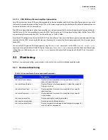
Page 51: ...FA input power using the show edfa command Use the EDFA control output gain command to restore the default 22dB EDFA gain if necessary Use a show raman command to find the current Raman gain setting then use the Raman control output gain command to adjust the Raman gain until the EDFA is at its optimal condition 3 3 Monitoring DarkStar show commands allow you to monitor system activity from either...

Page 52: ...39 19 Client 7 Up Down 10GE 40 0 dBm N A Alarm 1 18 40 49 Client 8 Up Down 10GE 19 1 dBm N A OK 1 18 40 49 Client 9 Up Down 10GE 18 8 dBm N A OK 1 18 40 49 Wave 0 Up Alarm 10GE 13 3 dBm 30 OK 0 22 02 21 Wave 1 Up Alarm 10GE 11 3 dBm 31 OK 1 18 40 49 Wave 2 Up Alarm 10GE 40 0 dBm 32 Alarm 1 18 40 49 Wave 3 Up Alarm 10GE 13 4 dBm 33 OK 1 18 40 49 Wave 4 Up Up 10GE 9 8 dBm 34 OK 0 21 23 51 Wave 5 Up ...

Page 53: ...ted Wavelength 1310nm I2C Address 0 5 80 General Status Administrative State Up Transmitter Disabled Receiver LOS Error Forwarding Laser Shutdown by Virtualight Total Down Error Time 153828s Time Since Last State Change 1 18 43 48 Last Cleared Time Stamp Jul 12 01 57 55 UTC I2C Transaction Error Count 0 Status Register Contents 0x4A00 Sensor Status Laser Temperature OK 3 3V Supply Voltage OK Rx La...

Page 54: ...m High Alarm 1 9dBm High Warning 0 9dBm Low Warning 7 0dBm Low Alarm 8 0dBm Tx Laser Bias Current 0 0mA High Alarm 85 0mA High Warning 80 0mA Low Warning 12 0mA Low Alarm 7 0mA CDR Temperature 39C CDR 3 3V Supply Voltage 3 37V BERT Status Receive Off Transmit Off Labcons2_DSM ...

Page 55: ... probably already damaged and will be shut off immediately to prevent possible damage to other DarkStar components In addition to the temperature sensors provided by individual components of the DarkStar system there is a shutdown sensor embedded in the DarkStar circuit board If the shutdown sensor reaches 70 C the DarkStar system will automatically power off disrupting switch board traffic The Da...

Page 56: ...ontents of the log buffer localhost show log 0 01 45 15 Authentication Success 10 15 1 98 0 01 46 17 Authentication Failure 10 15 1 98 0 01 46 22 Authentication Success 10 15 1 98 3 3 4 SNMP DarkStar systems support both the SNMPv1 and SNMPv2c versions of SNMP To monitor detailed DarkStar system status use the XKL proprietary SNMP management objects and traps defined in the current XKL MIB see htt...

Page 57: ...fic Trap Types Trap Trap Type Event 1 xklFanFail A fan module has failed or has some other problems 2 xklPowerFail A power supply module has failed or has some other problems 3 xklFanUp A fan module has come online 4 xklPowerUp A power supply module has come online 5 xklProtection PathSwitch A protection path APP switch has occurred 6 xklTempStatus Change Temperature status has changed 7 xklEDFALi...

Page 58: ... Error detection at optical frequencies is at the physical layer of the network stack DarkStar systems rely on signal integrity indicators from the laser interfaces and Clock and Data Recovery CDR circuitry to monitor and detect signal errors The most common indicators used to monitor the integrity of incoming optical signals in order of precedence are Loss of Signal LOS The optical power of a rec...

Page 59: ...receivers The signal integrity error is detected consistently further downstream Some modules may report incorrect statuses when error forwarding occurs Therefore it may be possible for different modules even if the modules are the same model to report different line statuses In the absence of client signals error forwarding across the wave interfaces may result in client equipment reporting unusu...

Page 60: ...d logging files Issue a bert transmit on the transmitting interface to initiate PRBS generation followed by a bert receive command that initiates checking of the PRBS stream begins counting errors and measures elapsed time Use show bert and show bert logging to verify that a BERT is running and to view BERT results 3 4 1 Configure BERT logging Before enabling BERT ensure that LOS and or LOL condit...

Page 61: ...it accumulates a count of samples If you configure the BERT as verbose then a new log entry is created for each sample even if Total Errors remains continuously at zero Test results are visible at the console or in log files In this example BERT logging is configured as verbose the BERT logging interval is set to 30 seconds the BERT is launched on the Client 1 interface using bert transmit and ber...

Page 62: ...d to verify a BER of 10 12 at 85 99 levels of confidence for a SONET and a 10GE link FIGURE 3 5 BERT test times required for BER 10 12 From the table on a SONET link at 9 953Gbps BERT test time needs to be at least 301 seconds in order to be 95 confident that its BER is better than 10 12 In general you calculate the minimum BERT test time by determining the required transmission bit count then div...

Page 63: ...the configuration file runs automatically at boot time It includes not only system and network settings but also configures management services such as SNMP and event logging that need to be in place for better troubleshooting As part of the running configuration you should Configure operator consoles and AAA authentication Use the tacacs server aaa authentication line and password commands Config...

Page 64: ...kl and xkl generic otherwise by default SNMP will send you all possible SNMP network traps Enable the AAA feature using the aaa new model command so that TACACS logs an auditable account of configura tion changes The log may help your diagnosis by showing who issued what commands in the period leading up to the crash A crash dump file dump dump exe is generated by default on an unscheduled restart...

Page 65: ... light is reaching them No system dump file is available 4 1 2 6 Manual crash recovery only if automatic recovery fails You will need to intervene manually in the boot process if the system can t restart due to a corrupt or invalid saved config file or corrupted system flash memory Intervene from the console by entering CTRL C before the boot process completes 4 1 2 7 Diagnosis You should be able ...

Page 66: ... older passwords Review and verify operator passwords in use No serial connection no activity at console Faulty cable connection Incorrect or faulty cable Check connection and reseat if necessary Replace with good cable Link LED is on but the activity LED remains off Wrong IP address assigned to Ethernet interface Ethernet ports administratively shut down Remote routing problems In CONF ETH mode U...

Page 67: ... connected Dirty fiber Failed laser or XFP SFP module s Connect with clean fiber Replace failed component DarkStar modules are hot swappable LOS Loss of Signal or LOL Loss of Lock on client or wave interfaces Incorrect encapsulation type Incorrect switch configuration Verify encapsulation types at transmit and receive endpoints and ensure they are the same System reports erroneous XFP SFP receive ...

Page 68: ...how led command shows these LED patterns at a remote operator console TABLE 4 3 LED Legend LED Status Meaning Steady off Steady on Flashing TABLE 4 4 Front Panel LED Patterns PWR green WRN amber ALM red Meaning No power or both power supplies down System fully operational One of the following conditions exists Maximum temperature exceeded FPGA load failure A load failure of both the startup and fa...

Page 69: ...strongly encourages you to maintain current copies of your configuration using the write memory and write network commands whenever configuration changes are made The following example shows system recovery using the boot command recovery switch Modify the example with installation specific values to implement recovery TABLE 4 5 Recovery Mode Commands Command Description configure Enter configure ...

Page 70: ...tch board 00085 01 Initializing DarkStar DSM10 5R Initializing environmental loader Running startup gateware Done Power NOT Cycled Mounting file system User Enabling TX laser on interface OSC 0 W User Enabling TX laser on interface OSC 1 E The system has entered recovery mode either due to startup flash read failure or manual user operation To prevent dropping customer traffic the software did not...

Page 71: ...tion about DarkStar system functions and network operations In a production network using debug can generate a high volume of trace information at the console and may degrade system performance so XKL recommends that You use the debug command only when working with XKL technical support to diagnose a specific problem with your system You avoid using the debug command in a production network The sy...

Page 72: ...50103 50003 10 ...

Reviews: