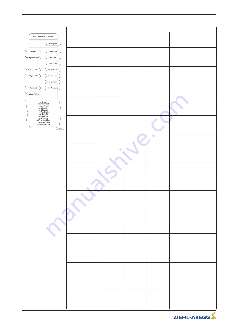
background image

Objekt Type #1

Open Loop Sensor 
Inputs/outputs

Type

Value range

Default

Description

nvoSpeed

SNVT_rpm 
(102)

0...65.534, 
0xFFFF

X

Measured absolute speed 

nvoAlarm

SNVT_a-
larm_2 (164)

X

Option

nvoError*

uint (1 Byte)

128 

 255, 0 

invalid

X

128 no fault > 128 fault code 
table

nvoRelais

SNVT_switch 
(95)

.value 0...200, 
255
.state 0,1 

X
X

Fault output. In case of fault 
.state = 1 and .value x 2 = 
Fault code

nviSpeedSelect

SNVT_lev_-
disc (22)

0..2

0

ST_OFF (0): nciSpeed1
ST_LOW (1): nciSpeed2
ST_MED (2): nciSpeed3 

nciEnable

SNVT_lev_-
disc (22)

ST_ON, 
ST_OFF

ST_OFF Fan blocked
ST_ON Fan enabled 

nciMaxSpeed

SNVT_rpm 
(102)

0...65.534, 
0xFFFF

1100

Maximal Speed 

nciMinSpeed

SNVT_rpm 
(102)

0...65.534, 
0xFFFF

0

Minimal Speed 

nciSpeed1

SNVT_lev_-
cont (55)

.value 0..200, 
255

0

Operating point 1 (day)

nciSpeed2

SNVT_lev_-
cont (55)

.value 0..200, 
255

0

Operating point 2 (night)

nciAutoNight

SNVT_lev_-
disc (22)

ST_ON, 
ST_OFF

ST_OFF Internal interval 
timer blocked
ST_ON Internal interval timer 
operational 

nviTime

SNVT_ti-
me_stamp 
(84)

System time

nciNightSrt

SNVT_ti-
me_stamp 
(84)

Night operation start time

nciNightEnd

SNVT_ti-
me_stamp 
(84)

Night operation end time

nvoContTemp**

uint (1 Byte)

0..255

X

Option

nvoPowerOut

SNVT_switch 
(95)

.value 0...200, 
255
.state 0,1

X

Power requirement (in %)

nvoVisual***

struct_visual

Summary of important nvo for 
faster queries

nvoParaResp***

SNVT_preset 
(94)

To allow easier / extended 
con

guration with ZIEHL-

ABEGG software and installa-
tion devices

viParaReq***

SNVT_preset 
(94)

nciSpeed3

SNVT_lev_-
cont (55)

.value 0..200, 
255

0

Operating point 3 (holiday)

nciOperationMode

SNVT_lev_-
disc (22)

0..2

0

ST_OFF (0): Static operation 
with nciSpeedx
ST_LOW (1): Dynamic opera-
tion with nviSpeedRel
ST_MED (2): Dynamic opera-
tion with nviSpeedAbs

nviSpeedRel

SNVT_lev_-
cont (55)

.value 0..200, 
255

nciSpeed1

Dynamic rotational speed 
speci

cation, relative

nviSpeedAbs

SNVT_rpm 
(102)

0...65.534, 
0xFFFF

nciSpeed1 

abs.

Dynamic rotational speed 
speci

cation, absolute

Operating Instructions 

Connection box ECblue (LON)

Electrical installation

L-BAL-E268-GB 1630 Index 003

Part.-No. 

8/10

Summary of Contents for ECblue

Page 1: ...Connection box ECblue LON Connection control fan MICRO FIT Operating Instructions L BAL E268 GB 1630 Index 003 Part No english ...

Page 2: ...unctions The connection box can be used to communicate with the fan controller ECblue fans can be integrated into existing LON networks A LON network of several ECblue fans can be built up The communication between the fans happens via LONWORKS TP FT10 3 3 Transport The device is packed ex factory to suit the transport method previously agreed Always use the original packaging materials when trans...

Page 3: ...n cut out and fastening hole as shown in the drawing Insert the device into the installation cut out from the front and secure with a screw Dimensions mm Operating Instructions Connection box ECblue LON Mounting L BAL E268 GB 1630 Index 003 Part No 3 10 ...

Page 4: ...n 0 5 1 5 mm 2 flexible with wire end ferrule 3 Line input connection box Wieland plug series GST 18i3 suitable socket part e g GST 18i3 S B1 Z R1 or GST 18i3 1 F B2 Z R1 4 LED green Operation Flashing error code see ECblue assembly instructions chapter Operating state display 5 LED red Fault see ECblue assembly instructions chapter operating state display 6 BUS1 RJ45 7 Service RJ45 8 BUS2 RJ45 9 H...

Page 5: ...ted to one another PIN 5 on BUS1 BUS2 and Service are only through connected to one another PIN 7 on BUS1 BUS2 and Service are through connected to one another 1 X1 a 2 X1 b 3 X1 c 4 X1 d 5 X1 e 6 X1 f 7 X1 g 8 X1 h 1 X3 a 2 X3 b 3 X3 c 4 X3 d 5 X3 e 6 X3 f 7 X3 g 8 X3 h 1 X2 a 2 X2 b 3 X2 c 4 X2 d 5 X2 e 6 X2 f 7 X2 g 8 X2 h NET_A NET_B n c n c V V NET_A NET_B NET_B NET_A n c n c n c n c V V V V ...

Page 6: ...ction box is always based on the bus topology With the recommended CAT5 patch cable the maximum cable length is 500 m Wiring and terminator in the LON network 5 4 2 Wiring and terminating resistor in the LON network With bus wiring a terminating resistor of 100 Ω 0 25 W must be fitted to the beinning and end of the line Information The stub lines to the individual devices should be kept as short as...

Page 7: ...to enable the motor controller function The variables nvoVisual nvoParameter and nviParameter are available for use with ZIEHL ABEGG software and installation devices For dynamic operation i e operation in which the speed changes very often e g control applications a different operating mode has to be selected as the static rotational speed specifications nciSpeedx only allow a limited number of wr...

Page 8: ...d ST_ON Internal interval timer operational nviTime SNVT_ti me_stamp 84 System time nciNightSrt SNVT_ti me_stamp 84 Night operation start time nciNightEnd SNVT_ti me_stamp 84 Night operation end time nvoContTemp uint 1 Byte 0 255 X Option nvoPowerOut SNVT_switch 95 value 0 200 255 state 0 1 X Power requirement in nvoVisual struct_visual Summary of important nvo for faster queries nvoParaResp SNVT_...

Page 9: ...uts down Switching back on is only possible by re applying the mains voltage 135 Hall sensor error Starting retried after approx 1 minute 136 Overcurrent fault Motor shuts down Starting retried after approx 1 mi nute 150 external communication error Motor continues running with last set values 158 Supply voltage too high overvolt age Motor shuts down Starting retried if undervoltage no longer exis...

Page 10: ...our technical support for control systems ventilation technology phone 49 0 7940 16 800 Email fan controls service ziehl abegg de Our worldwide contacts are available in our subsidiaries for deliveries outside of Germany see www ziehl abegg com If you make returns for inspections or repairs we need certain information in order to facilitate focused trouble shooting and fast repair Please use our r...

Reviews: