IntelliPack Series 892M/894M Computation Transmitter User's Manual DC Voltage/Current Input
___________________________________________________________________________________________
- 7 -
Table 3B: Int
elliPack 89xM Math Functions…continued
FUNCTION
DESCRIPTION
OR(n1,n2,..,n5)
Conditional construct OR of two to five
channels, numbers, or expressions.
True if any one or more of n1..n5 are
true. Can only be used inside the
conditional expression for IF.
<
Conditional construct -less than.
<=
Conditional construct -less than or equal
to.
>
Conditional construct -greater than.
>=
Conditional construct -greater than or
equal to.
=
Conditional construct -equal to.
<>
Conditional construct -not equal to.
Notes (Table 3):
1. In the table, “
n
” is used to represent a channel variable,
number, or expression (another function or equation).
2. Do not use the plus symbol as a polarity indicator, it is only
used for the add operation.
3. Do not type or embed space between the sign of a number
and the number itself.
4. Do not type or embed space between the function keyword
and left parenthesis.
Show Simulator
The IntelliPack Configuration Software also provides a Show
Simulator function that you can use to test your formula and
ensure that a correct output response within range is produced,
without having to drive the inputs with real world signals. For
each input, a slider control is provided to simulate the input
signal. For fine control of the slider, use the left and right arrow
keys. The corresponding output value is displayed using scaled
units, and signal units (voltage or current). Error checking in this
area is limited and it is up to the user to verify correct output
formulation for all possible conditions of input. As such, use of
the Show Simulator function is highly recommended for critical
control applications. Computations that return values beyond the
defined range will be “clipped” to the minimum or maximum
scaled values to ensure that a valid output response is always
returned.
The following example equations are entered into the
Equation field exactly as they are shown below.
Equation Examples
Compute the average of 4 signals -
(A + B + C + D)/4
Compute the smallest square root of 3 input signals -
MIN(SQRT(ABS(A)), SQRT(ABS(B)), SQRT(ABS(D)))
Compute the square of the scaled value of channel 1 -
POWER(A,2)
Compute the sum of the minimum and maximum of 4 signals -
MIN(A, B, C, D) + MAX(A, B, C, D)
Compute the maximum of 4 different signals greater than 10 -
MAX(A, B, C, D, 10)
Conditional expression examples -
IF(AND(A>B,C=D)) THEN(A*2) ELSE(B*3)
IF(OR(A>=B,A=D)) THEN(A) ELSE(C) - 12.56
When formulating an equation or response, it is important to
keep the limits of module resolution in mind (see Table 5). In
some cases, it may be necessary to normalize your variables or
output response. Always use the Show Simulator function to test
your equation over the full range of input to ensure a valid output
response. A computation that returns a value beyond the defined
range will be “clipped” to the minimum or maximum scaled values
to ensure a valid response is always returned. Due to memory
constraints of the module, some equations may be too complex
and an error will be indicated in the Show Simulator screen.
HOLD Function
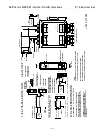
This module also includes a HOLD input terminal that affects
the output response. With HOLD deasserted (set HIGH or left
open with respect to COM terminal), the output will track the
result of the input equation. However, if HOLD is asserted (set
LOW or shorted to COM), then the output will remain at the result
of the last computation until HOLD is deasserted. Note that the
input HOLD signal is driven with respect to input COM. Input
COM and RTN are not the same potential and should never be
connected together, either directly or through ground. Do not
ground COM.
4.0 THEORY OF OPERATION
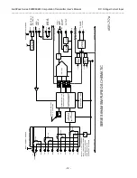
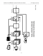
Refer to Simplified Schematic 4501-717 and Functional Block
Diagram 4501-718 to gain a better understanding of the circuit.
Note that this transmitter will pre-filter a signal and convert the
signal to a scaled voltage--either through a voltage divider circuit
(voltage input), or a current sink resistor (current input). An A/D
converter stage then applies appropriate gain to the signal,
performs analog-to-digital conversion, and digitally filters the
signal. The digitized signal is then transmitted serially to a
microcontroller. The microcontroller completes the transfer
function according to its configuration and programmed equation,
and then sends a scaled output signal to an optically isolated
Digital-to-Analog Converter (DAC). The DAC then updates its
current or voltage output in response. If HOLD is asserted, then
the output will remain at the last value until HOLD is deasserted.
With HOLD deasserted (set HIGH or left open), the output will
track the result of the input equation. The embedded
configuration and calibration parameters are stored in non-volatile
memory integrated within the microcontroller. Only the functions
required by an application are actually stored in memory
—new
functionality can be downloaded via the IntelliPack Configuration
Program and Serial Port Adapter. A wide input range switching
regulator (isolated flyback mode) provides is5V and +16V
power to the circuit, plus an is15V output circuit supply.

