Preliminary Information
Banner Engineering Corp
•
Minneapolis, MN USA
www.bannerengineering.com
•
Tel: 763.544.3164
Sensonix Incorporated
•
Plymouth, MN USA
7 of 18
www.sensonix.com
•
763.519.7042
2.6 ModBus Communications, RS232 / 485 (model LPGW1)
The gateway interface is controlled using the Modbus RTU protocol. The gateway device operates as
a Modbus slave device with a programmable slave address in the range of 01-99. The serial interface is set
up with factory default parameters of 19.2k baud, one start bit, two stop bits, no flow control and a slave
address of ‘01’.
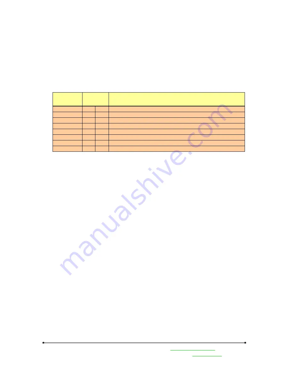
The following Modbus function codes are supported. For DX80 configuration commands and DX80
user commands refer to the
DX80 Interface Protocol document
.
Type
Function
Code
Description
Modbus Cmd
1
0x1
Read Coils, 1 – 2000 contiguous status of coils
Modbus Cmd
2
0x2
Read Discrete Inputs, 1 – 2000 contiguous status of discrete inputs
Modbus Cmd
3
0x3
Read Holding Registers, 1 – 125, contiguous block of holding regs.
Modbus Cmd
4
0x4
Read Input Registers, 1 – 125, contiguous block of input registers
Modbus Cmd
5
0x5
Write Single Coil
Modbus Cmd
6
0x6
Write Single Register
Modbus Cmd
15
0xF
Write Multiple Coils, 1 – 0x7B0 force multiple coils, ON or OFF
Modbus Cmd
16
0x10 Write Multiple Registers, 1 – 0x78, contiguous block of registers
The gateway front panel LED’s are used to display information about the Modbus serial
communications.
LED1
•
‘GREEN’ when power is applied and the gateway is operational.
•
‘RED’ indicates a system error has occurred. Review the LCD display for further
information.
LED2
•
‘YELLOW’ signifies a frame reception or sending.
•
‘RED’ signals an internal Modbus error has occurred.
•
Flashing ‘RED’ indicates a communications fault or configuration error.
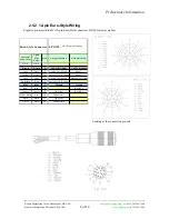
The RS485 connections are on the 12-pin euro-style male connector QD2 on the gateway. See the Euro
Connector Diagram section in this manual


