WAM Arm – User’s Manual
support@barrett.com
www.barrett.com
© 2008 Barrett Technology®, Inc.
Document: D1001, Version: AH.00
64 of 80
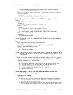
Equation 1 below gives the transform between two adjacent D-H coordinate frames. The D-H
parameters that were derived from this equation are located in Table 4 and Table 5 below. Note
that
c
and
s
stand for
cos
and
sin
respectively.
⎟⎟
⎟
⎟
⎟
⎠
⎞
⎜⎜
⎜
⎜
⎜
⎝
⎛
=
Τ
−
1
0
0
0
c
s
0
s
a
s
c
-
c
c
s
c
a
s
s
c
s
-
c
1
i
i
i
i
i
i
i
i
i
i
i
i
i
i
i
i
i
i
i
d
α
α
θ
α
θ
α
θ
θ
θ
α
θ
α
θ
θ
Equation 1 – D-H generalized transform matrix
Table 4 – 4-DOF WAM frame parameters
(with blank outer link installed)
Table 5 – 7-DOF WAM frame parameters
i
a
i
α
i
d
i
θ
i
i
a
i
α
i
d
i
θ
i
1
0
−π/2
0
θ
1
1
0
−π/2
0
θ
1
2
0
π/2
0
θ
2
2
0
π/2
0
θ
2
3
0.045
−π/2
0.55
θ
3
3
0.045
−π/2
0.55
θ
3
4
−0.045
π/2
0
θ
4
4
−0.045
π/2
0
θ
4
Τ
0
0
0.35
5
0
−π/2
0.3
θ
5
6
0
π/2
0
θ
6
Notes:
−
Units of meters and radians
7
0
0
0.06
θ
7
−
T = Tool frame
Τ
0
0
0
For example, to generate the transform from coordinate Frame 2 to coordinate Frame 1 (i.e. the
position and orientation of Frame 2 described in terms of Frame 1 which is also a rotation about
joint 2), use the parameters in the second row of Table 4 as follows:
⎟⎟
⎟
⎟
⎟
⎠
⎞
⎜⎜
⎜
⎜
⎜
⎝
⎛
=
Τ
1
0
0
0
)
0
(
)
2
/
(
cos
)
2
/
(
sin
0
)
0
)(
(
sin
)
2
/
(
)sin
cos(
-
)
2
/
(
)cos
cos(
)
sin(
)
0
)(
(
cos
)
2
/
(
)sin
sin(
)
2
/
(
)cos
sin(
-
)
cos(
2
2
2
2
2
2
2
2
2
1
π
π
θ
π
θ
π
θ
θ
θ
π
θ
π
θ
θ
⎟⎟
⎟
⎟
⎟
⎠
⎞
⎜⎜
⎜
⎜
⎜
⎝
⎛
=
Τ
1
0
0
0
0
0
1
0
0
)
cos(
-
0
)
sin(
0
)
sin(
0
)
cos(
2
2
2
2
2
1
θ
θ
θ
θ
Equation 2 – D-H Matrix Example


