background image

Website:-www.bholanath.in

E-mail id:-support@bholanath.in

24

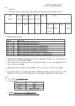
15.Single register Commands:

SET_HOME_POSITION:

Slave Address

Function Code

Holding ADDR

Op-Code

01

06

0x25

04

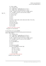
Note:
Command: 01, 06, 00,25,00,04

01 -> Slave Address
06* -> Function Code
00* -> LSB Address of Holding Register
25* -> MSB Address of Holding Register
00, 04* -> Op-code for SET_HOME position

(* indicates these values are fixed

)

Response: 01, 06, 00,25,00,04

START: Start

Slave Address

Function Code

Holding ADDR

Op-Code

01

06

0x25

05

Note:
Command: 01, 06, 00,25,00,05

01 -> Slave Address
06* -> Function Code
00* -> LSB Address of Holding Register
25* -> MSB Address of Holding Register
00, 05* -> Op-code for START the motor

(* indicates these values are fixed

)

Response: 01, 06, 00,25,00,05

Summary of Contents for BH-SMART-2A

Page 1: ...Website www bholanath in E mail id support bholanath in 1 User s Manual For BH SMART 2A Micro Stepping Driver ...

Page 2: ...ACE RS 485 DRIVE HAVING INBUILT RPM DIRECTION CONTROL BY ROTARY SWITCH WITH ON OFF SWITCH BHOLANATH 1 DC power input 10VDC 45VDC 2 Output current 0 25A 2A 3 Micro stepping 200 400 800 1600 3200 4 Protect From overheat lock automatic half current error connect protect 5 Dimension 97mmx64mmx31mm 6 Weight 150g 7 Working environment Temperature 15 C 45 C ...

Page 3: ...itch 5 Wiring Notes 6 Switch Choices 6 4 Sequence Chart Of Control Signals 6 5 Calculation of pulse frequency 7 Frequency With Different RPM At 400 Micro Step 7 Frequency With Different RPM At 800 Micro Step 7 6 Connecting the Motor 7 Connections to 4 lead Motors 7 Connections to 6 lead Motors 8 Half Coil Full Coil Configurations 8 Connections to 8 lead Motors 9 Series Parallel Connections 9 7 Pow...

Page 4: ...oil 17 Write Single Bit Parameter Relay 17 14 Single Register Parameters 18 CONNECT DISCONNECT COMMAND 19 SLAVE ADDRESS 19 MICROSTEP 20 PITCH 21 CURRENT 21 ACC 22 DCC 23 BAUDRATE 23 15 Single register Commands 24 SET_HOME_POSITION 24 START Start 24 HOLD Hold 25 RELEASE Release 25 SET_DEFAULT_CODE 25 16 Multiple register Write commands 26 RUN 27 MOVE 28 GO_HOME 29 17 Auto cycle programming 30 AUTO_...

Page 5: ...ble for a wide range of stepping motors for NEMA size 17 It can be used in various kinds of machines such as X Y tables And a variety of large scale automation equipments and instruments For example labeling machine cutting machine packaging machine plotter engraving machine CNC machine tools and so on It always performs well when applied for equipment which requires for low vibration low noise hi...

Page 6: ...l and Switch 1 Clockwise and Anticlockwise movement of Rotary wheel will give Clockwise and Anticlockwise motion of motor 2 To increase speed continue to rotate the wheel in same direction 3 Once desired speed is achieved press the switch once to record the data the motor will stop 4 Now you can use the switch for ON OFF as per requirement and the saved data will be used to rotate the motor 5 Long...

Page 7: ...Microstep 3200 microstep will be set 4 Sequence Chart of Control Signals In order to avoid some fault operations and deviations PUL DIR and ENA should abide by some rules shown as following diagram NOTE Enable signal is always high in this drive Any external supply of 5 Vdc applied will disable the Drive Remark a t1 ENA must be ahead of DIR by at least 5uS ENA signal is necessary to be driven High...

Page 8: ...xible but easiest to wire Speed and torque will depend on winding inductance Connections to 6 lead Motors Like 8 lead stepping motors 6 lead motors have two configurations available for high speed or high torque operation The higher speed configuration or half coil is so described because it uses one half of the motor s inductor windings The higher torque configuration or full coil uses the full w...

Page 9: ...de at higher speeds In series mode the motors should also be run at only 70 of their rated current to prevent overheating 8 lead motor series connections Parallel Connections An 8 lead motor in a parallel configuration offers a more stable but lower torque at lower speeds But because of the lower inductance there will be higher torque at higher speeds 8 lead motor parallel connections 7 Power Supp...

Page 10: ...ng the OFF duration Therefore the average current withdrawn from power supply is considerably less than motor current Multiple Drivers It is recommended to have multiple drivers to share one power supply to reduce cost if the supply has enough capacity To avoid cross interference DO NOT daisy chain the power supply input pins of the drivers Instead please connect them to power supply separately 8 ...

Page 11: ... the motor wiring Motor or drive failure Replace the motor or drive Motor rotates in Motor phases connected in Reverse the phases line the wrong reverse direction Wrong I p direction signal Change direction setting Motor line break Change the phases are connected Inaccurate The Micro steps set incorrectly Set the correct segments The motor load is too heavy Increasing the current Position Control ...

Page 12: ...t run motor without holding torque RESET signal is effective when offline Make RESET ineffective Motor doesn t run but Without input pulse signal Adjust PMW signal level maintains holding torque Too small relative to current Correct rated current setting setting Motor s holding torque is Acceleration is too fast Reduce the acceleration too small Motor stalls Rule out mechanical failure Driver does...

Page 13: ...UT Connection OR 11 Circuit connections Of BH SMART 2A With BH SDC 01 SDC 02 FAULT FAULT V GND FAULT O P STATUS O P FAULT FAULT GND V FAULT O P STATUS O P R R NOTE Maximum Current through the Fault Switch Is 10 mAmp Up to 12V no external resister required BH SMART BH SMART ...

Page 14: ...Website www bholanath in E mail id support bholanath in 14 12 Circuit Connections Of BH SMART 2A With PLC ...

Page 15: ...Website www bholanath in E mail id support bholanath in 15 This is a Tentative connection Guideline for driving the Drive from Any 5V Controller Systems ...

Page 16: ...single 16 bit register value and for Modify Write more than one register Multiple register value using function code 0x10 When Motor drive run in Auto cycle Mode Input relays are used to control cycle start stop these are single bit values So that to modify switch status function code 0x05 For each cycle state start at and stop at output coils status is read by using function code 0x01 Read Parame...

Page 17: ... 2 Bytes 1 to 2000 0x7D0 Response Function code 1 Byte 0x01 Byte count 1 Byte 2 x N Coil Status n Byte n N or N 1 N Quantity of Outputs 8 if the remainder is different of 0 N N 1 Error Error code 1 Byte Function code 0x80 Exception code 1 Byte 01 or 02 or 03 or 04 Function code 1 Byte 0x06 Starting Address 2 Bytes 0x0000 to 0xFFFF Register Value Data 2 Bytes 0x0000 to 0xFFFF Function code 1 Byte 0...

Page 18: ...unction code 1 Byte 0x05 Starting Address 2 Bytes 0x0000 to 0xFFFF Output Value 2 Bytes 0x0000 or 0xFF00 Response Function code 1 Byte 0x05 Starting Address 2 Bytes 0x0000 to 0xFFFF Output Value 2 Bytes 0x0000 or 0xFF00 Error Error code 1 Byte 0x85 Exception code 1 Byte 01 or 02 or 03 or 04 14 Single Register Parameters ...

Page 19: ...SB 00 Holding Register Address MSB 00 01 Connect to device op code indicates these values are fixed Response 01 06 00 00 00 01 SLAVE ADDRESS The following command is used to change the slave address Device ID In this for Broadcast id 0 Zero used to send command to all devices connected over MODBUS It has limitation that for broadcast address there will be no any response So PC application does get...

Page 20: ...1 06 00 04 00 07 MICROSTEP This command is used to set micro steps Micro steps can be read by using function code 0x03 Slave Address Function Code Holding ADDR Data 1 6 0x1A MICROSTEP Note Micro step value MICROSTEP VALUE 0x01 Full Step 0x02 Half Step 0x04 step 0x08 1 8 Step 0x16 1 16 Step Note Red Coloured values are not applicable Command 01 06 00 1A 00 04 01 Slave Address 06 Function Code 00 LS...

Page 21: ...ue is 1mm in linear mode indicates these values are fixed Response 01 06 00 22 00 64 LINEAR Value should be multiplied by 100 and compounded to integer e g 10 5 mm should be sent as 1050d 00 00 04 1A in HEX CURRENT This command is used to set Current Current can be read by using function code 0x03 The current value is Hex code value not current in ampere selected from application drop down current...

Page 22: ...mmand is used to set Acceleration Acceleration can be read by using function code 0x03 Acceleration value is multiplied by 10 as float value required more number of bytes Slave Address Function Code Holding ADDR Data 01 06 0x0C ACC Note ACC value 2 Byte 14 55 to 59590 Step sec2 for Driver Note Command 01 06 00 0C 00 01 01 Slave Address 06 Function Code 00 LSB Address of Holding Register 0C MSB Add...

Page 23: ...Holding Register 0D MSB Address of Holding Register 00 01 DEC value indicates these values are fixed Response 01 06 00 0D 00 01 BAUDRATE This command is used to set or Change Baud rate Slave Address Function Code Holding ADDR Data 01 06 0x01 BR BR BR VALUE BPS 0x00 1200 0x01 1800 0x02 2400 0x03 4800 0x04 7200 0x05 9600 0x06 19200 0x07 38400 0x08 57600 0x09 72000 0x0A 115200 0x0B 128000 Note Comman...

Page 24: ... Holding Register 25 MSB Address of Holding Register 00 04 Op code for SET_HOME position indicates these values are fixed Response 01 06 00 25 00 04 START Start Slave Address Function Code Holding ADDR Op Code 01 06 0x25 05 Note Command 01 06 00 25 00 05 01 Slave Address 06 Function Code 00 LSB Address of Holding Register 25 MSB Address of Holding Register 00 05 Op code for START the motor indicat...

Page 25: ...s 06 Function Code 00 LSB Address of Holding Register 25 MSB Address of Holding Register 00 07 Op code for HOLD the motor indicates these values are fixed Response 01 06 00 25 00 07 RELEASE Release Slave Address Function Code Holding ADDR Op Code 01 06 0x25 08 Note Command 01 06 00 25 00 08 01 Slave Address 06 Function Code 00 LSB Address of Holding Register 25 MSB Address of Holding Register 00 0...

Page 26: ...esponse 01 06 00 25 00 0A 16 Multiple register Write commands These commands are used in Manual Mode Address 1 Byte Address 1 Byte Register Number of Register Default Value Range in Value of Register Decimal 0 to 255 hex 0 to FF each Register is 16 bit hex Decimal for configuration 37 0x25 MB_RUN_CMD 5 0x0000 Speed 20 bit value DIR 1 FW Speed unit 0 REV step tick 37 0x25 MB_MOVE_CMD 5 0x0000 No of...

Page 27: ...ddress 10 Function Code 00 LSB Address of Holding Register 25 MSB Address of Holding Register 00 03 Quantity of registers to be write in holding register 06 Total Byte count to be write in run command 01 Op Code for RUN command 01 Counter clockwise direction 00 Speed is in RPM 00 00 C8 total Speed value that is 200 rpm indicates these values are fixed Response 01 10 00 25 00 03 Slave Function Hold...

Page 28: ...ltiplication in short please send the Primary Values Only Note No of Steps 0 to 4194303 value Unit of Speed Unit of Speed VALUE 0x00 RPM 0x01 RPH 0x02 MM_PER_SEC SPEED Ranges from 5 to 4780 RPM Rotary Mode Ranges from 5 to 4780 RPM Linear Mode Slave Function Holding QTY of Byte Op Code Data Address Code ADDR Register Count 1 10 0x25 5 0A 2 DIR and Unit of Speed No of MovementSpeed Steps Type Value...

Page 29: ...r MOVE command 06 Counter clockwise direction with movement type of Step input 00 Speed is in RPM 00 00 C8 total Speed value that is 200 rpm 00 00 01 90 No of steps 400 steps indicates these values are fixed Response 01 10 00 25 00 05 GO_HOME Parameters Passed unit of speed Speed Slave Function Holding QTY of Byte Op Code Data Address Code ADDR Register Count 1 10 0x25 3 6 3 unit of Speed speed No...

Page 30: ...ion Code 00 LSB Address of Holding Register 25 MSB Address of Holding Register 00 03 Quantity of registers to be write in holding register 06 Total Byte count to be write in run command 03 Op Code for GO_HOME command 00 Speed is in RPM 00 00 00 C8 total Speed value that is 200 rpm indicates these values are fixed Response 01 10 00 25 00 03 ...

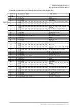
Page 31: ...17 Auto cycle programming The following table give the message format for auto cycle programming This message used to send one auto cycle program We can send one by one cycle program to device ...

Page 32: ...Website www bholanath in E mail id support bholanath in BHOLANATH PRECISION ENGINEERING PVT LTD Page 32 ...

Page 33: ...TIME in CCW 14 With GEAR Rotary Movement with TIME in CW 18 With GEAR Rotary Movement with STEPS in CCW 1C With GEAR Rotary Movement with STEPS in CW 28 Without GEAR Rotary Movement with ANGLE in CCW 2C Without GEAR Rotary Movement with ANGLE in CW 30 Without GEAR Rotary Movement with TIME in CCW 34 Without GEAR Rotary Movement with TIME in CW 38 Without GEAR Rotary Movement with STEPS in CCW 3C W...

Page 34: ...tus of current cycle Outputs Switch Low High 1 00 1 2 00 2 3 00 4 4 00 8 5 00 10 6 00 20 7 00 40 8 00 80 Note If user needs to apply MOVE Commands with gear configurations then PRIMARY GEAR and SECONDARY GEAR values must be set before AUTO Cycle Program ANGLE Value should be multiplied by 100 and compounded to integer e g 30 56 should be sent as 3056d 00 00 0B F0 in HEX Time Value is in Second Fac...

Page 35: ...rection 02 Acceleration 02 Deceleration 00 Speed in RPM 00 00 64 100 Rpm in hexadecimal 00 00 01 90 400 steps in hexadecimal value 11 Start the cycle at switch 1 high 13 Stop the cycle at switch 2 high 00 No output 00 No output indicates these values are fixed Response 01 10 00 2A 00 08 Instructions The Holding Register address of next cycle number use following formula Holding Register address Ho...

Page 36: ...t 00 Stop cycle direct 00 No output 00 No output indicates these values are fixed Response 01 10 00 32 00 08 Command for Cycle 3 for GO_HOME 01 10 00 3A 00 08 10 01 02 02 02 00 00 00 64 00 00 00 00 00 00 00 00 01 Slave Address 10 Function Code 00 LSB Address of Holding Register for Cycle 1 32 MSB Address of Holding Register for Cycle 2 00 08 Quantity of registers to be write in holding register 10...

Page 37: ... Bit 2 SW3 442 1BA SWITCH 1 0x00 Bit 3 SW4 STATUS Bit 4 SW5 Bit 5 SW6 0 OFF Bit 6 SW7 1 ON Bit 7 SW8 Function code Bit Address Relay State OFF ON 0x05 0x0001 to 0x0007 0x0000 or 0xFF00 Example SW1 is Made ON Command 01 05 00 01 FF 00 01 Slave Address 05 Function Code 00 LSB Address of Holding Register Bit Address 01 MSB Address of Holding Register Bit Address FF 00 Value State Of switch Response 0...

Page 38: ...A 00 08 10 02 14 02 02 00 00 00 64 00 00 00 02 00 00 00 00 AUTO C1 RUN CW TIME 2SEC 100RPM 10 00 32 00 08 10 03 01 00 00 00 00 00 00 00 00 00 00 00 00 00 00 delay 1SEC 10 00 3A 00 08 10 04 10 02 02 00 00 00 64 00 00 00 02 00 00 00 00 AUTO C1 RUN CCW TIME 2 SEC 100RPM 10 00 42 00 08 10 01 01 00 00 00 00 00 00 00 00 00 00 00 00 00 00 DELAY 1 SEC JMP TO CYCLE1 06 00 25 00 0A SET AS DEFAULT CODE 06 00...

Page 39: ...u may need this documentation to refer back to at a later date and these details will greatly assist our Technical Support staff in determining the problem should you need assistance Many of the problems that affect motion control systems can be traced to electrical noise controller software errors or mistake in wiring The content in this manual has been carefully prepared and is believed to be ac...

Reviews: