background image

CS230/CS231 Temperature Profiler 

Outputs of both lifetime and user resettable minimum and maximum 

temperatures are also available during powered operation from each 

temperature point in the CS230/CS231. The user-resettable minimum and 

maximum temperatures can be used to monitor specific seasons or periods of 

measure, without having to review the entire data set. The lifetime minimum 

and maximum temperatures are used for maintenance and warranty records. 

The lifetime and user-resettable minimum and maximum temperature values 

are single 1-second readings.  

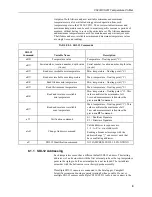
TABLE 8-1.  SDI-12 Commands 

SDI-12 

Command 

Variable Name 

Description 

aR0! 

Temperature value 

Temperature – floating point (°C)  

aR1! 

Serial number, location number, depth value 

(in cm) 

Serial number, location number, depth value 

(in cm) 

aR2! 

Read user resettable min temperature 

Min. temperature – floating point (°C)  

aR3! 

Read user resettable max temperature 

Max. temperature – floating point (°C)  

aR4! 

Read lifetime min temperature 

Min. temperature – floating point (°C)  

aR5! 

Read lifetime max temperature 

Max. temperature – floating point (°C)  

aR6! 

Read and reset user resettable 

min temperature 

Min. temperature – floating point (°C). This 

value constitutes the minimum of all 


1-second measurements taken since the 

previous 

aR6!

 command. 

aR7! 

Read and reset user resettable 

max temperature 

Max. temperature – floating point (°C). This 

value constitutes the maximum of all 


1-second measurements taken since the 

previous 

aR7!

 command. 

aV! 

Verification command 

S1 = BootRom Signature 

S2 = Firmware Signature 

aAb! 

Change Address command 

Valid addresses in sequence are: 
1–9 / A–Z / a–z (no Address 0)  
Sending a broadcast message with the 

address change “{” can correct units that 

have conflicting addresses. 

aI! 

SDI-12 Identification command 

X13CAMPBELLCS230 1.0 SN:XXXXX 

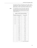
8.1.1  SDI-12 Addressing 

Each temperature sensor has a different default SDI-12 address. The starting 

addresses is 1 and coincides with the first external probe or the top temperature 

point in the rigid probe if an external probe is not included. The last address 

coincides with the bottom sensor in the rigid probe assembly.  

If multiple SDI-12 sensors are connected to the data logger, Campbell 

Scientific recommends using separate terminals when possible. However, 

multiple SDI-12 sensors or multiple CS230/CS231 sensors can connect to the 

Summary of Contents for CS230

Page 1: ...CS230 CS231 Temperature Profilers Revision 1 19 Copyright 2016 2019 Campbell Scientific...

Page 2: ......

Page 3: ...under guarantee or not Please state the faults as clearly as possible and if the product is out of the guarantee period it should be accompanied by a purchase order Quotations for repairs can be give...

Page 4: ......

Page 5: ...digital cell phones and aerials may also not be applicable according to your locality Some brackets shields and enclosure options including wiring are not sold as standard items in the European marke...

Page 6: ......

Page 7: ...beginning work Wear a hardhat and eye protection and take other appropriate safety precautions while working on or around tripods and towers Do not climb tripods or towers at any time and prohibit cl...

Page 8: ......

Page 9: ...uction 8 7 4 2 Slow Sequence Program Instructions 8 8 Operation 8 8 1 Sensor Measurements 8 8 1 1 SDI 12 Addressing 9 8 1 2 Metadata 11 8 2 Long Cables 11 8 3 Power Conservation 11 9 Maintenance Calib...

Page 10: ...3 Line Surge Protector Mounting and Wiring D 1 Figures 7 1 CS231 installation example with three external sensors and five internal sensors 6 7 2 Internal sensor label 6 D 1 SGB3 3 line surge protecto...

Page 11: ...r its resistance to temperature extremes moisture and UV degradation However this jacket will support combustion in air It is rated as slow burning when tested according to U L 94 H B and will pass FM...

Page 12: ...sor in the Sensors Temperature folder Double click CS230 CS231 SDI 12 Temperature Profiler Type the correct Starting SDI 12 Address for the first external probe or the top temperature point in the rig...

Page 13: ...ta logger check the output of the sensor in data display in LoggerNet PC400 RTDAQ or PC200W to make sure it is making reasonable measurements 5 Overview The CS231 offers the same precise temperature p...

Page 14: ...Specifications Features Accurate and stable measurements Each sensor is individually addressed and referenced to its depth Low power consumption Digital SDI 12 output Compatible with the following da...

Page 15: ...ent it is important that consistent contact be made between the temperature profiler and the medium The location of the temperature profiler should be representative of the intended application Typica...

Page 16: ...and five internal sensors FIGURE 7 1 is an example configuration with three external sensors and five internal sensors Each profiler is custom built to the user s specific requirements FIGURE 7 2 sho...

Page 17: ...the CS230 serial number is less than 1162 TABLE 7 1 Wire Colour Function and Data Logger Connections Wire Colour Function Data Logger Connection Terminal Red Power 12V Green SDI 12 Signal C or U1 term...

Page 18: ...tonTimeout are optional parameters refer to CRBasic Help for more information 7 4 2 Slow Sequence Program Instructions Use the slow sequence program instructions when the CS230 CS231 measurements will...

Page 19: ...floating point C aR6 Read and reset user resettable min temperature Min temperature floating point C This value constitutes the minimum of all 1 second measurements taken since the previous aR6 comma...

Page 20: ...tiple sensors the same SDI 12 address will prevent the sensors from communicating Use the aA command where a is the affected address to reset the affected sensors to their factory configured address v...

Page 21: ...een the temperature profiler and data logger digitally there are no offset errors incurred with increasing cable length as seen with analogue sensors However with long enough cable lengths the digital...

Page 22: ...non switched for test purposes Symptom Sensor won t respond to command 1 Expected address not used or has been changed a Confirm all addresses in use with the aI command to determine the individual ad...

Page 23: ...Cut program following the procedure in Section 4 QuickStart p 1 Finish the program On the Advanced tab click the CRBasic Editor button The program opens in CRBasic with the name noname CR_ Provide a n...

Page 24: ......

Page 25: ...in the probe will need to be adjusted to fit specific application Const NumTempSensors 15 Uses the control terminal C1 on the CR1000X Const SDI12_Port C1 Public TempC NumTempSensors As Float Dim i As...

Page 26: ...terval Other common station data is measured every 5 seconds and stored to a daily and hourly data tables CRBasic Example B 2 CR1000X Program Using Slow Sequence to Read CS230 CS231 with 20 Sensors CR...

Page 27: ...tion ConvertSDI12addr EndSub Main Program BeginProg Scan 5 Sec 0 0 PanelTemp PTemp 250 Battery batt_volt CallTable Daily CallTable Hourly NextScan Poll CS230 CS231 in Slow Sequence every minute SlowSe...

Page 28: ...ables DataTable MetaData 1 1 DataInterval 0 1 Day 10 Sample MetaData_pts Meta FP2 EndTable Define Subroutines ConvertSDI12addr Convert SDI 12 character address 0 9 A Z and a z to number value 0 61 Fun...

Page 29: ...minimum and maximum are recorded every 5 minutes and Metadata is collected daily Declare Public Variables Public PTemp batt_volt Enter the number of temperature sensors that are in the probe will need...

Page 30: ...order Meta i 1 SDI12_Port ConvertSDI12addr i R1 1 0 0 Next EndIf Read the current Temperature Min and Max Values Every 5 minutes and Reset the Value If TimeIntoInterval 0 5 Min Then For i 1 To NumTemp...

Page 31: ...s C 2 SDI 12 Command Basics SDI 12 commands have three components Sensor address a a single character and the first character of the command Use the default address of zero 0 unless multiple sensors a...

Page 32: ...ber or other sensor specific information may also be included aI allccccccccmmmmmmvvvxxx xx CR LF a Sensor SDI 12 address ll SDI 12 version number indicates compatibility cccccccc 8 character vendor i...

Page 33: ...ated with the M command The response to each command has the form atttn CR LF where a sensor address ttt time in seconds until measurement data is available When the data is ready the sensor notifies...

Page 34: ...rs of data in response to a D command that follows an M command Command aD0 aD1 aD9 Response a values CR LF or a values CRC CR LF where a the sensor address values values returned with a polarity sign...

Page 35: ...ect All Caps Mode 6 Press Enter until the data logger responds with the CR1000 prompt 7 Type SDI12 and press Enter 8 At the Select SDI12 Port prompt type the number corresponding to the control termin...

Page 36: ......

Page 37: ...Vac L1 L2 L3 with respect to G terminals Maximum Current 2 A per terminal 4 A total requires both ground terminals for return current Maximum Rated Surge 1200 A 8 20 us D 2 SGB3 3 Line Surge Protector...

Page 38: ...logger using the 2 ft cable shipped with the CS230 2 U terminals are automatically configured by the measurement instruction If multiple SDI 12 sensors are connected to a data logger Campbell Scienti...

Page 39: ......

Page 40: ...Asia Location Bangkok Thailand Email info campbellsci asia Website www campbellsci asia China Location Beijing P R China Email info campbellsci com cn Website www campbellsci com cn Spain Location Ba...

Reviews: