12
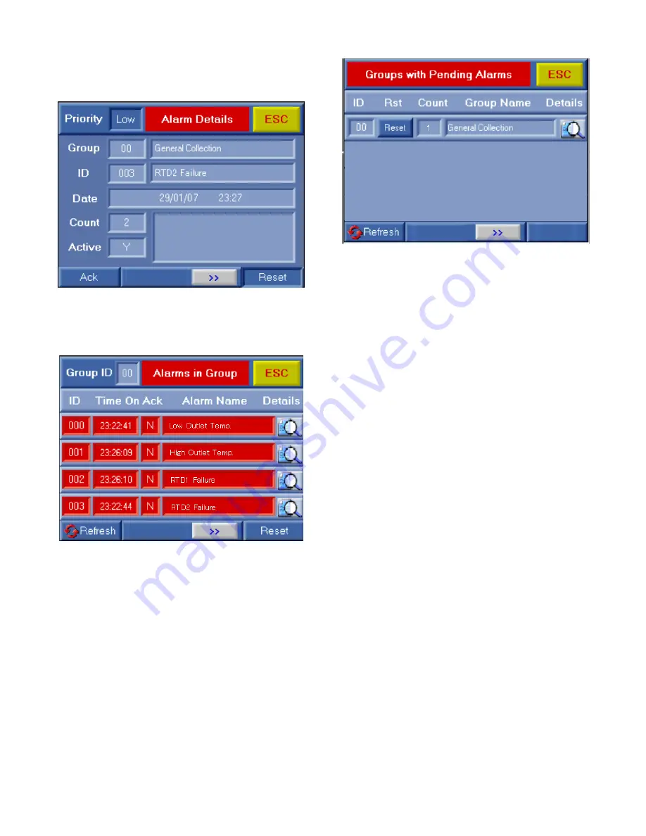
“Ack” button will acknowledge the alarm. Pressing “ESC”
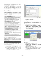
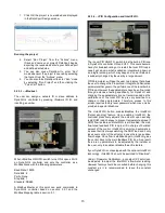
takes the user through two more screens, namely “Alarms
in Group” and “Groups with Pending Alarms”.
“Alarms in Group” lists a summary of all the alarms active
in DynaFLO in one page, if there is more than one active
alarm. However this page does not go into as much detail
for each alarm as “Alarm Details” page.
“Groups with Pending Alarms” would show all the groups of
alarms that have an active alarm, however in DynaFLO all
alarms are under Group 00 and therefore this alarm page
will always only list Group 00 if there is ever an active alarm.
Pressing the “ESC” button one more time from here will
then take the user back to the Start-Up screen.
Alternatively through the registers listed in Modbus Map
table in section 5.1, a Modbus Master Is notified about each
specific alarm in the group that is triggered. The Modbus
Master is also notified if in general there is one or more
active alarms. The Modbus Master can also ACK and Clear
all alarms provided that all the conditions of triggering the
alarms are satisfied. If not satisfied, even if Modbus Master
acknowledges and clears the alarms, the alarms show up
again instantaneously since the condition that triggered
them is not yet satisfied. It should be noted that if Modbus
Master acknowledges and clears alarms, alarms are also
cleared from the <Alarm History> which is explained in the
next section. The corresponding registers relating to alarms
are tabulated in the Modbus Map table in section 5.1.
As mentioned in section 4.4, two digital outputs are
associated with alarms, O0 and O1. Whenever there is an
active alarm, regardless of the alarm acknowledged or not,
O1 will come on and it will stay on for as long as the new
alarm remains active even if it becomes acknowledged, O1
will go off when alarm is satisfied. This digital output is
suitable for use with remote systems such as a BMS
(Building Management System) or with a building alarm
panel, buzzers or etc. O0 however will switch between ON
and OFF whenever there is a new unacknowledged alarm.
And once the alarm is acknowledged it turns to a solid ON.
And once the alarm is satisfied it will go OFF. This output is
therefore recommended for connecting to an alarm light to
follow the sequence that was just described. The electrical
wiring of these two digital outputs is explained in section 4.4
and in Appendix B.
5.2.3
–
<Setup> (Installer Level Password: 3232)
5.2.3.1
– <Alarm Configuration>
When in <Alarm Configuration> low limit and high limit for
DHW outlet temperature can be selected. Once these
selections are made, <Setpoint> in <Control> cannot take
a value higher than <High Outlet Temp. Alarm> or a value
lower than <Low Outlet Temp. Alarm>. If the DHW outlet
temperature rises above the value chosen in <High Outlet
Temp. Alarm>, a new alarm will activate after <Outlet Temp.
HL Time Delay> seconds. Similarly if the DHW outlet
temperature falls below the value chosen in <Low Outlet


