-18-
5.4 Creating a Message
A message consists of (1) Slave address, (2) Function code, (3) Data section and (4) Error check code. (See
Section 5.3)
The message readable or writable at one time is within the following range.
Data type
Number of data pieces
Floating data
60
Other than floating data
120
How to create a message will be described by an example given below.
Example) Reading a measured data for SE3000 series field scanners Channel 1 with "slave address 02".
5.4.1 RTU mode message
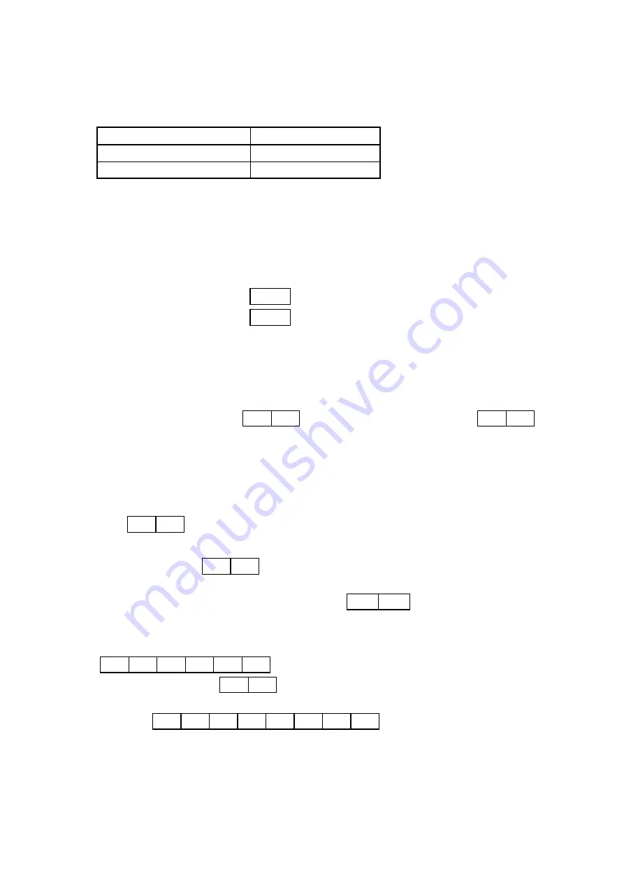
(1) Slave address : 02
(
02H
)
(2) Function code : 04
(
04H
)
The data type is "Read analog input data (read input register contents)". When the function code is "04",
specify the “data's Relative No. by 2 bytes" and the "number of data pieces by 2 bytes" to be read from the
data section. (See Section 5.5. See Section 5.5.4 for "Function code: 04".)
* It is necessary to make sure of the number of bytes of data.
(3) Data section :
Starting Relative No. 100 (
00H 64H
) and Number of data pieces 2 (
00H 02H
)
Measured data (analog input data) are stored in Reference Nos. "30001 to 40000" (See Table 3 in Section
5.3.4). The reference table shows that the integer part of CH1 is stored in "30101" and the decimal place in
"30102". (See Section 5.7. See Section 5.7.3 for reading the measured data.)
The Relative No. of the starting "Reference No. 30101” is 30101 - 30001 = 100 that can be expressed by 2
bytes " 00H
64H ".
The number of data pieces to be read is "2" of the integer part of CH No.1 and the decimal place, which
can be expressed by " 00H
02H " in 2 bytes
(4) Error check: 2730H calculated with CRC-16 ( 30H
27H )
Error check in RTU mode is calculated with CRC-16. (See Section 5.3.5.1)
The data in the core message is:
"
02H
04H
00H
64H
00H
02H " according to (1) to (3), whose CRC-16 is 2730H.
Error check data is therefore 30H 27H .
(5) Message:
02H
04H
00H
64H
00H
02H
30H
27H
Create a message according to the message configuration. (See Section 5.3)


