background image

Programmable DC Electronic Load 63600 Series Operation & Programming Manual 


5-42 


Query Example: 

CONF:VOLT:LATC? 


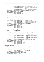
CONFigure:VOLTage:LATCh:RESet 


Type: 


Channel-Specific 


Description: 


Resets the Von signal. 


Setting Syntax: 

CONFigure:VOLTage:LATCh:RESet 


Setting Parameters:None. 


Setting Example:  CONF:VOLT:LATC:RES  

Resets the Von Signal. 


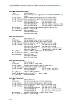
CONFigure:VOLTage:OFF 

Type: 


Channel-Specific 

Description: 

Set the voltage of sink current off. 

Setting Syntax: 

CONFigure:VOLTage:OFF<space><NRf+>[suffix] 

Setting Parameters:Refer to respective specification for valid value range. 
Setting Example: 

CONF:VOLT:OFF 0.5 


Set Voff = 0.5V 


CONF:VOLT:OFF 500mV 


Set Voff = 0.5V 

CONF:VOLT:OFF MAX 

Set Voff = maximum value. 

CONF:VOLT:OFF MIN   


Set Voff = minimum value. 


Query Syntax:  

CONFigure:VOLTage:OFF?[<space><MAX | MIN>] 


Return Parameters:<NR2>,  [Unit = Volt] 


Query Example: 

CONF:VOLT:OFF? 

CONF:VOLT:OFF? MAX 


CONF:VOLT:OFF? MIN 


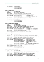
CONFigure:VOLTage:ON 

Type: 


Channel-Specific 

Description: 

Set the voltage of sink current on. 

Setting Syntax: 

CONFigure:VOLTage:ON<space><NRf+>[suffix] 

Setting Parameters:Refer to respective specification for valid value range. 
Setting Example: 

CONF:VOLT:ON 0.5 


Set Von = 0.5V 


CONF:VOLT:ON 500mV 


Set Von = 0.5V 

CONF:VOLT:ON MAX 

 Set Von = maximum value. 

CONF:VOLT:ON MIN 


Set Von = minimum value. 


Query Syntax:  

CONFigure:VOLTage:ON?[<space><MAX | MIN>] 


Return Parameters:<NR2>,  [Unit = Volt] 


Query Example: 

CONF:VOLT:ON? 

CONF:VOLT:ON? MAX 


CONF:VOLT:ON? MIN 


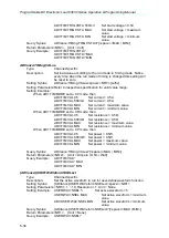
CONFigure:VOLTage:RANGe 


Type: 


Channel-Specific 


Description: 


Set the voltage measurement range in CC mode. 


Setting Syntax: 

CONFigure:VOLTage:RANGEe<space><CRD | NR1> 


Setting Parameters:<CRD | NR1>, LOW | L | 0, MIDDLE | M | 1, HIGH | H | 2 
Setting Example: 

CONF:VOLT:RANG HIGH    


Set voltage range to High. 


CONF:VOLT:RANG M   


Set voltage range to Middle. 


CONF:VOLT:RANG 0 


Set voltage range to Low. 

Query Syntax: 

CONFigure:VOLTage:RANGe? 

Return Parameters:<CRD>, LOW, MIDDLE, HIGH 


[Unit = None] 

Query Example: 

CONF:VOLT:RANG? 


Summary of Contents for 63600 Series

Page 1: ......

Page 2: ......

Page 3: ...Programmable DC Electronic Load 63600 Series Operation Programming Manual Version 2 2 July 2017...

Page 4: ...a ATE INC shall not be held liable for errors contained herein or direct indirect special incidental or consequential damages in connection with the furnishing performance or use of this material CHRO...

Page 5: ...or operations repairs will be billed at cost Chroma assumes no responsibility for its product being used in a hazardous or dangerous manner either alone or in conjunction with other equipment High vo...

Page 6: ...ective 2011 65 EU indicates that the level of the specified chemical substance exceeds the threshold level specified in the standards of SJ T 11363 2006 and EU Directive 2011 65 EU Remarks The CE mark...

Page 7: ...1 Chroma is not fully transitioned to lead free solder assembly at this moment however most of the components used are RoHS compliant 2 The environment friendly usage period of the product is assumed...

Page 8: ...vi...

Page 9: ...vii...

Page 10: ...viii...

Page 11: ...ix Warning This is a class A product In a domestic environment this product may cause radio interference in which case the user may be required to take adequate measures...

Page 12: ...ESSITY OF PROTECTIVE GROUNDING Never cut off the internal or external protective grounding wire or disconnect the wiring of protective grounding terminal Doing so will cause a potential shock hazard t...

Page 13: ...nd is not explicitly stated This symbol indicates the power connector does not provide grounding Frame or chassis To identify a frame or chassis terminal Alternating Current AC Direct Current DC Alter...

Page 14: ...ting Network Parameter IP Subnet Mask Gateway Confirming Network Connection is Successful and Communicating with Instruments in the chapter of Remote Operation Apr 2010 1 3 Add the followings Digitizi...

Page 15: ...otice in the section of Remote Sensing Connections Add the contents of Select the current range in the section of Setting CR Values Modify the syntax description in the sections of CONFIGURE Subsystem...

Page 16: ......

Page 17: ...ainframe Connections 2 10 2 7 Remote Control Connection 2 11 2 8 GPIB Card Setup 2 11 2 9 Ethernet Card Setup 2 12 3 Operation Overview 3 1 3 1 Introduction 3 1 3 2 Front Panel Description 3 2 3 3 Rea...

Page 18: ...ynamic Function 4 25 4 6 3 Setup of OCP Test Function 4 25 4 6 4 Setup of Program Sequences Function 4 27 4 6 5 Running the Program Sequences Function 4 33 4 6 6 MPP Tracker 4 33 4 6 7 User Defined Wa...

Page 19: ...stem 5 70 5 3 2 13 PROGRAM Subsystem 5 72 5 3 2 14 RESISTANCE Subsystem 5 78 5 3 2 15 RUN Subsystem 5 80 5 3 2 16 SHOW Subsystem 5 80 5 3 2 17 SYNCHRONOUS Subsystem 5 81 5 3 2 18 SPECIFICATION Subsyst...

Page 20: ...10 7 3 4 2 Checking Medium Power Range 7 10 7 3 4 3 Checking Low Power Range 7 11 7 3 5 Dynamic Slew Rate Circuit Test 7 12 7 3 5 1 Checking Dynamic Constant Current High Range 7 13 7 3 5 2 Checking...

Page 21: ...00 15 63640 80 80 63640 150 60 etc are all the same except the variations on input voltage load current and power ratings An individual module may have one or two channels Each channel has its own cha...

Page 22: ...Programmable DC Electronic Load 63600 Series Operation Programming Manual 1 2 Figure 1 1 63600 5 Mainframe Mounted with 5 Load Modules...

Page 23: ...General Information 1 3 Figure 1 2 63601 5 Mainframe Mounted with 5 Load Modules Figure 1 3 63600 2 Mainframe Mounted with 2 Load Modules Figure 1 4 63600 1 Mainframe Mounted with 1 Load Module...

Page 24: ...ble DC Electronic Load 63600 Series Operation Programming Manual 1 4 Figure 1 5 63610 80 20 Load Module Figure 1 6 63630 80 60 Load Module Figure 1 7 63640 80 80 Load Module Figure 1 8 63630 600 15 Lo...

Page 25: ...solation offers true floating Load Automatic fan speed control to reduce noise The maximum standby noise is 63dB 1 Up to 10 channels for one Mainframe 1 3 2 Load Constant current CC constant resistanc...

Page 26: ...250V Frequency 47 to 63 Hz Maximum VA 300VA Weight 15 6kg 34 39lbs Dimension Width 447 mm 17 6 inch Height 177 mm 7 0 inch without foot stand 194 8 mm 7 7 inch with foot stand Depth 554 2 mm 21 8 inc...

Page 27: ...idity before loading the current 6 The specifications of DC current accuracy are tested after the input is applied for 30 seconds 7 The pollution degree of the equipment is 2 8 The power of the 63600...

Page 28: ...2 FS Dynamic Mode CC Min Operating Voltage 11 1 5V 1 5V Frequency 100Hz 50kHz 0 01Hz 1kHz 100Hz 50kHz 0 01Hz 1kHz Duty 1 99 Min Rise Time Dominated 1 99 Min Rise Time Dominated Accuracy 1 s 1ms 100pp...

Page 29: ...No of bits 2 bits per mainframe 2 bits per mainframe External Trig for Digitizing TTL Compatible Rising edge No of bits 1 bit per mainframe 1 bit per mainframe External Trig for Auto Sequences TTL Com...

Page 30: ...2 FS Dynamic Mode CC Min Operating Voltage 11 3V 1 5V Frequency 100Hz 50kHz 0 01Hz 1kHz 100Hz 50kHz 0 01Hz 1kHz Duty 1 99 Min Rise Time Dominated 1 99 Min Rise Time Dominated Accuracy 1 s 1ms 100ppm...

Page 31: ...2 bits per mainframe 2 bits per mainframe External Trig for Digitizing TTL Compatible Rising edge No of bits 1 bit per mainframe 1 bit per mainframe External Trig for Auto Sequences TTL Compatible Ris...

Page 32: ...ff Control 13 Von Voff Mode CC CR CP Accuracy 0 2 FS Dynamic Mode CC Min Operating Voltage 11 16 1 8V Frequency 100Hz 50kHz 0 01Hz 1kHz Duty 1 99 Min Rise Time Dominated Accuracy 1 s 1ms 100ppm Slew r...

Page 33: ...O P Level TTL Compatible Level Active High Short ON O P No of channels 2 channels per 63600 1 mainframe 4 channels per 63600 2 mainframe 10 channels per 63600 5 mainframe 6 channels per 63601 5 mainf...

Page 34: ...the SI unit of conductance equal to one reciprocal ohm NOTE 10 Ext Wave Mode CC minimum driving current is 0 2mA NOTE 11 It is the minimum voltage of load measured by Oscilloscope NOTE 12 It is the cu...

Page 35: ...General Information 1 15 1 5 Dimension Outline of 63600 Series 63600 5 Mainframe outline with 5 Load Modules Unit mm...

Page 36: ...Programmable DC Electronic Load 63600 Series Operation Programming Manual 1 16 63601 5 Mainframe outline with 5 Load Modules Unit mm...

Page 37: ...General Information 1 17 63600 2 Mainframe outline with 2 Load Modules Unit mm 16 10 553 85 210 00 16 10 177 00 177 00 35 38 10 05 UNIT mm 63600 2...

Page 38: ...Programmable DC Electronic Load 63600 Series Operation Programming Manual 1 18 63600 1 Mainframe outline with single Load Module Unit mm...

Page 39: ...General Information 1 19 Module outline Unit mm 142 85 62 510 36 6 32 UNIT mm 63610 80 60 63610 80 80...

Page 40: ......

Page 41: ...lish W38 000023 Test Wire Red Black G32 341000 Binding Post Fixer W33 000033 White Load Wire W33 000035 White Load Wire Fuse 2A 250V Fuse 5A 250V W51 000028 Y type Bare Terminal 13 8mm Y type Bare Ter...

Page 42: ...ite load wire W33 00035 75cm 2 pieces Test wire red black 2 pieces each Y type bare terminal exradius 10 8mm 4 pieces 63630 80 60 63640 80 80 White load wire W33 00033 75cm 1 piece Test wire red black...

Page 43: ...63640 80 80 63640 150 60 Loads can be combined in the Mainframe in any order The module installation procedures for all Mainframes are the same No special tools are required to install Load Module to...

Page 44: ...g Modules in the Electronic Load If the Mainframe is not installed with all modules the empty slot must be covered with the panel cover for safety and airflow To unplug it lift up the switch between t...

Page 45: ...ithin temperature range from 0 to 40 degree C However you must install the Electronic Load in an area that has enough space around for adequate air flowing through and escaping from the back You must...

Page 46: ...with the correct pin connected to ground Power on the Load by the front panel switch on Mainframe and observe the display Immediately after turning on the Electronic Load executes a self test that che...

Page 47: ...on the module to the LOW potential output terminal of the power supply UUT Figure 2 4 illustrates the typical setup of the Load module to the UUT The connecting way is First Put the Y type terminal wi...

Page 48: ...Programmable DC Electronic Load 63600 Series Operation Programming Manual 2 8 Figure 2 4 Load Remote Sensing Connection...

Page 49: ...asurement Figure 2 4 also illustrates a typical setup for remote sensing operation The potential of Vsense red connector must be higher than that of Vsense black connector Due the nature of load the a...

Page 50: ...dules depends only on total modules available in the multi mainframe environment described in the next section Figure 2 6 Parallel Connection 2 6 4 Multi Mainframe Connections The Electronic Load syst...

Page 51: ...puter The GPIB and Ethernet interface of the electronic load is optional Connect the Remote Controller to the Electronic Load before powering it on If you have not done this Load will shut down or the...

Page 52: ...0 Series Operation Programming Manual 2 12 2 9 Ethernet Card Setup The mainframe 63600 2 63600 5 and 63601 5 facilitate remote operation via Ethernet bus as an option Setting up Ethernet card and its...

Page 53: ...tant impedance CZ etc An individual module may have one or two channels Each of them has its own channel number with its own input connectors and can be turned on off or short circuited independently...

Page 54: ...Mainframe front panel includes a 2 characters 7 segment LED display and keypads The front panels of Mainframe 63600 5 63601 5 63600 2 63600 1 are shown in Figure 3 1 Figure 3 2 Figure 3 3 and Figure 3...

Page 55: ...cludes two System Bus ports a USB port an optional GPIB connector an optional Ethernet connector a System I O port an AC LINE socket a fuse holder and five air holes of the fan cooling The rear panels...

Page 56: ...ration Programming Manual 3 4 Figure 3 5 Rear Panel of 63600 5 Figure 3 6 Rear Panel of 63601 5 GPIB USB SYSTEM BUS ETHERNET SYSTEM I O FUSE AC Socket FAN COOLING AIR HOLE FAN COOLING AIR HOLE SYSTEM...

Page 57: ...d to module with isolation 6 Fuse Safe guard against over loading 7 AC Line AC power connector that supplies power to all modules in the mainframe 8 Fan Cooling Air Holes Air holes with metal fan guar...

Page 58: ...module s input is momentarily disabled before a new mode is enabled This ensures the minimum overshoots during mode change The parameters in current resistance or voltage mode can be programmed easil...

Page 59: ...state If the CC mode of Load module is active the new setting will change the input immediately at a rate determined by the slew rate setting Static Load Mode In CC mode two operation modes Static lo...

Page 60: ...on the Load module Slew Rate Rise Fall A s or mA s Slew rate determines the rate at which the current input of a module change to a newly programmed value There are two slew rate values which are rise...

Page 61: ...eration the loading value is switched between those two load levels according to such user specified parameters Frequencies Start frequency End frequency Step frequency Hz The setting range of the Fre...

Page 62: ...f low middle or high range The low range is used for input voltage in low voltage range The middle range is used for input voltage in middle voltage range while the high range is for input voltage ove...

Page 63: ...average calculation process for the measuring data High frequency parts will be removed and the minimum transient time of the loading current in this mode is 400 s Voltage can be programmed in any of...

Page 64: ...ts will be removed and the minimum transient time of the loading current in this mode is 400 s Power can be programmed in any of low range middle or high range by the key The low power range is operat...

Page 65: ...UT Ip max value needs to be set before loading and the parameter range for setting is listed in the specifications To avoid the load current change caused by the input voltage variation the power sour...

Page 66: ...the actual transition time The minimum transition time is from 10 s in the CC mode and CC dynamic mode slew rate setting In order to prevent the voltage transient of UUT from damaging the Load the ele...

Page 67: ...down near the Von voltage When you set the conducting voltage Voff the Load will start sinking current when the load is ON and the UUT output voltage reaches the Von voltage and stop sinking current...

Page 68: ...l return to the previous programmed values when the short circuit is turned off In order to simulate a real short circuit the electronic short function is only available in each mode for High current...

Page 69: ...Setting the Configuration is over to leave out of the page of system configuration you need to press and simultaneously to quit the Setting page of system configuration 3 12 Timing Measurement Functi...

Page 70: ...t waveform and Ch2 is the voltage waveform of the UUT AC component Figure 3 20 The dynamic current loading bandwidth varies with the load designed on the market and the response speed of loading slow...

Page 71: ...gram 1 is set up with 5 sequences and program 2 is set up with 8 sequences the rest programs from 3 to 10 can set up the remaining 87 sequences Please see section 4 6 5 for setting and running the Pro...

Page 72: ...protection occurs Over Temperature Protection Each Load has an over temperature protection circuit which will turn off the load if internal temperature exceeds the safety limit The over temperature O...

Page 73: ...vershoot even though the Von point is set to 0V or the voltage is suddenly dropped to 0V and raised again This way is to prevent the overshoot to damage the UUT and Electronic Load When high voltage m...

Page 74: ...this circumstance as shown in Figure 3 25 Figure 3 25 When Von Point sets to 0V with Protection 3 When the Von Point is not set to 0V and protection is selected for LVP during LOAD ON turn off the SW...

Page 75: ...for all channels can be saved and recalled for various test setup use In the Save file 00 99 each file has the settings of Configure CC CR CV CP CZ CCD CCFS TIMING SINE WAVE DYNAMIC and OCP TEST with...

Page 76: ...xcept that the Period control signals are not generated internally but are inputted from V EXT Connectors are on the rear panel A 0 to 10V external signal corresponds to the 0 to full scale input rang...

Page 77: ...ule allows the user to enter specification of a UUT including V I Watt for later GO NG check In addition the real time measurement bar on the VFD display indicates the degree of deviation from spec an...

Page 78: ...lock feature in order that the stored data will only be erasable by authorized user When data lock is enabled any data enter is prohibited and this LED indicator lights up when any data key is presse...

Page 79: ...key for 3 seconds can save the profile automatically 9 Power Switch Main power switch 4 2 2 Front Panel Keys and Indicators of the Load Module There are two types of panels in Load module single chan...

Page 80: ...operation 4 Indicates the Electronic Load is in Dynamic load operation 5 Indicates the Electronic Load is in short circuit simulation for UUT to test short protection 6 This indicates the SPEC inspec...

Page 81: ...ion mode for power supply testing Press MODE repeatedly will switch the mode in the sequence of CC CR CV CP CZ accordingly for users to edit and test The system provides programmable dynamic loading f...

Page 82: ...on Press and hold this key for 3 seconds to save is the Default of any mode This key is used to trigger the short circuit function Active at load ON status This key is used to start or stop sinking cu...

Page 83: ...3 Selecting the Channel for a Dual Channel Module The key is used to select one of the channels for a dual channel module like the model Chroma 63610 80 20 To edit the channel settings you must select...

Page 84: ...CC operation high current range middle current range and low current range The current levels are programmed in milliamps at low range and in Amps at middle range and high range The slew rate levels a...

Page 85: ...ion of the value changes according to the rotary knob turning speed 4 Set Slew Rate There are 500 discrete steps in each range Press the key to set slew rate of rise Turn the Rotary knob to change the...

Page 86: ...t high middle or low 3 types of ranges ALL resistance levels are programmed in ohms The following examples show how to set the CR values of Load module for model 63630 80 60 1 Select the resistance ra...

Page 87: ...b to change the value of that digit If the user does not use or key to display the cursor then resolution of the value changes according to the rotary knob turning speed 5 Set the second Resistance Le...

Page 88: ...is as follows High range Middle range Low range goes back to High range 2 Select state A B for single channel module For single channel module press the key to select state A or state B then the LED...

Page 89: ...three response speeds for CV mode CURR_PSU fast normal and slow for different UUTs testing Their response time is Fast 3ms Normal 10ms Slow 50ms Turn the Rotary knob to change the speed until the desi...

Page 90: ...y until the LED L above the key lights up The sequence of range selection after pressing key is as follows High range Middle range Low range goes back to High range 2 Select state A B for single chann...

Page 91: ...gle channel module Press the key to select State B then the LED B above the key lights up Turn the Rotary knob to change the display value to 6 watts then press key to confirm 6 0000 W 6 Review and up...

Page 92: ...user may use or key to change the cursor position to different digit of data then turn the rotary knob to change the value of that digit If the user does not use or key to display the cursor then res...

Page 93: ...ion of the data edit key must be pressed Otherwise pressing the key new data will not be written into the internal memory the previous value for the parameter is kept 6 Quit from editing mode Press to...

Page 94: ...The current levels are programmed in milliamps at low range and in Amps at middle range and high range The slew rate levels are programmed in mA s at low range and in A s at middle range and high rang...

Page 95: ...to display the cursor then resolution of the value changes according to the rotary knob turning speed Notations for Load1 and Load2 are and respectively values for Load1 and for Load2 have nothing to...

Page 96: ...Then the display will go to the first editing page again 6 Review and update the values of the setting parameters Review the values of the setting parameters by pressing key Update them by set new val...

Page 97: ...y until the LED of the desired range above the key is lights up High range is used when higher current level is required and LOW range is used when better resolution is required Select Middle range by...

Page 98: ...1s The VFD displays DWELL 0 100 s Then press key to confirm the setting At the same time it changes to setting Duty 5 Set Duty The duty can be set from 1 99 but the Duty setting will be limited withi...

Page 99: ...e these powerful functions you must set relevant parameters in accordance with application needs To set the Advance function you need to press to enter into the page of Advance function the VFD displa...

Page 100: ...he conduction voltage level TRG_S It sets the start trigger voltage level for measurement time TRG_E It sets the end trigger voltage level for measurement time The Electronic Load will measure the dur...

Page 101: ...DYNA screen can set the parameters required for I_DC I_AC and FREQ I_DC is the DC bias current and I_AC is the peak to peak current generated based on the I_DC The setting range of FREQ is 0 01Hz 200...

Page 102: ...key to confirm the setting END_I 60 000 A 3 Set Step of Current Change Set the step of current change between initial Current Level and final Current Level The setting range of the step is from 1 to 1...

Page 103: ...ecution The Electronic Load has 10 programs 1 10 and they share 100 sequences The user can use the program chain function to chain each set of program and create various sequences combinations For exa...

Page 104: ...n N Yes No Yes No Save Program Set Range Set Range Set Range Set Range LIST STEP Set Program Chain Set Program Repeat Clear All Set Total seq Number Set Sequence Trig Mode Set Sequence Run Mode Set SR...

Page 105: ...displayed on the VFD Then press key to select type and confirm the setting TYPE LIST 3 Setting the Program Chain The chain function of program enables you to chain program so as to get more sequences...

Page 106: ...xecution SKIP Skip the sequence Load will not change input status AUTO When Dwell time passes the Load will get to the next sequence automatically MANUAL Press key to confirm then the Load will get to...

Page 107: ...ange the display value to 0 2A s then press key to confirm SR 0 20 A s SR 0 20 A s g Setting the Sequence P F Specification The Electronic Load allows the user to program specification of a UUT for la...

Page 108: ...time The default setting is 0s P F_DLY 1 s 9 Review and update the values of the setting parameters Review the values of the setting parameters by pressing key Update them by set new value in their s...

Page 109: ...he display shows as follows 01 004 CCM RUN 4 9963V 1 3686A Once the execution of Auto sequences is done the panel will show the items not within the specifications SPEC NG SEQ 01 001 01 002 01 003 01...

Page 110: ...Programmable DC Electronic Load 63600 Series Operation Programming Manual 4 34...

Page 111: ...ameters in accordance with application needs for configuration setup This procedure is needed for initial setup only The configuration of each channel is stored separately in the EEPROM of Mainframe T...

Page 112: ...n voltage The default setting for Von voltage is 0V Von_POT 00 000V Set Von latch There are two operation modes for Von control Von latch ON means the Load will sink current continuously when it reach...

Page 113: ...Voff should be less than or equal to Von The default setting for Voff voltage is 0V Vof_POT 00 000V Set CV mode type There are two operation modes in CV mode Current PSU and Voltage PSU This option i...

Page 114: ...play The Electronic Load will show minus sign for the voltage if you select MINUS It will not show any sign if you select PLUS The default setting is PLUS The displayed digits are five but select MINU...

Page 115: ...system configuration you need to press and simultaneously to go back to the page of system configuration 4 7 2 Setup of Specification The Electronic Load allows the user to program specification of a...

Page 116: ...ER HIGH and LOW The CENTER level must be set by the value of channel input reference level The HIGH and LOW levels can be set by the value or percentage selected in configuration SPEC MODE The HIGH LO...

Page 117: ...OR ON Setting the NETWORK parameters Please refer to Chapter 5 for Ethernet LAN in the system You can set the LAN parameters including 1 DHCP on off 2 IP address 3 Gateway IP address and 4 Subnet Mask...

Page 118: ...TE edit page of system configuration you need to press and simultaneously to go back to the page of system configuration 4 7 4 Setup of Parallel The following is Operation Flow CONFIG Parallel Mode Mo...

Page 119: ...arallel edit page of system configuration you need to press and simultaneously to go back to the page of system configuration 4 7 5 Setup of Synchronous Dynamic Mode The following is Operation Flow CO...

Page 120: ...out of accuracy of specifications 2 The fastest refresh time for LOAD panel is 0 5 second When operating in SYNC DYNA if the T1 or T2 time is less than 0 5 second the change of panel reading is restri...

Page 121: ...iguration list on panel Underline indicates factory default Item1 Item2 Item3 Setting CONFIGURE 1 SETUP CC_VRANGE HIGH Von_POT 000 00V Von_LATCH OFF Vof_POT 000 00V CV_TYPE VOLT_PSU ALL_RUN ON EXT_WAV...

Page 122: ...ary knob to change the display value to 8 then press key into Display Model Information page of system configuration Display the Load model and serial number Display the model number of Load module It...

Page 123: ...fault setting of Sampling Time is 40ms Set the Sampling Point Set the sampling points The range is from 1 to 4 096 points The default setting of Sampling Point is 4 096 points Set the Trigger point Se...

Page 124: ...IG It indicates the Digitizing is waiting for the trigger signal POST_TRIG It indicates the Digitizing is processing Sampling Points Local operation It shows PRE_TRIG WAIT_TRIG under the DIGI INITIATE...

Page 125: ...ing File Default To save the entire present mode settings of all channels in the specified files 00 to 99 All saved settings are stored in EEPROM and will not be lost when ac power is cycled The memor...

Page 126: ...defined as follows Table 4 7 System Bus Connector Pin Number Signal Description 8 DGND Ground 9 SYNCW Output Signal Note When in Synchronous Dynamic Mode the SYNCW will change by T1 T2 When in T1 the...

Page 127: ...Load OFF and vice versa both of the signals need to be LOW to become Load ON When DI1 or DI2 is set to Remote Inhibit and is Low all channels in FRAME are Load off and a REMOTE INHIBIT protection mes...

Page 128: ...e They are defined as follows Figure 4 11 63600 2 System I O Port Connector Table 4 9 63600 2 Pin Assignments of the System I O Port Connector Pin No Signal Pin No Signal 1 EXT_WAVE1 14 EXT_WAVE2 2 EX...

Page 129: ...L When the SPEC is ON if all channels are determined as No Good the DO will output LOW level signal or it will remain at HIGH level e OTP OVP OCP OPP REV H If the load has any one of the OTP OVP OCP O...

Page 130: ...rst or second channel Output range is from 0 to 10V 7 AGNDC Analog signal reference ground 4 14 Using the Synchronous Cable 63600 Series supports up to 4 sets of mainframe synchronous load control see...

Page 131: ...al resistors of the rest mainframes need to be turned off Press and at the same time to enter into the CONFIGURE page Select 3 REMOTE and press to go to REMOTE page and select 2 SYSTEM BUS to set the...

Page 132: ......

Page 133: ...es 5 1 2 GPIB Capability of the Electronic Load GPIB Capability Response Interface Functions Talker Listener All electronic load functions except the setting for GPIB address are programmable via the...

Page 134: ...e is installed Power on the DC Electronic Load after connected it with the PC via USB cable and the user can use the 63600 Series SCPI commands through NI VISA to communicate with the DC Electronic Lo...

Page 135: ...ided into Site LAN and Private LAN Site LAN usually refers to large local area network such as enterprise network also called as Intranet including network server DHCP WINS DNS etc and terminal device...

Page 136: ...users can use the following two ways to connect to computer 1 2 Private LAN is a smaller local area network composed of two or more terminal devices and Hub or two terminal devices via Crossover Cable...

Page 137: ...t it to ON STEP 2 Press or directly to go to APPLY option and set it to YES then confirm the setting STEP 3 The screen will show the networking setting status The status messages are shown below a Ini...

Page 138: ...2 Press or directly to go to APPLY option and set it to YES then confirm the setting STEP 3 The screen will show the networking setting status The status messages are shown below a Initiating The netw...

Page 139: ...Remote Operation 5 7 STEP 1 Click Control Panel on the PC and double click Network Connections to enter it STEP 2 Select Local Area Connection and click right mouse button to select Properties...

Page 140: ...63600 Series Operation Programming Manual 5 8 STEP 3 Select Internet Protocol TCP IP and click Properties STEP 4 Select Use the following IP address that is to set the IP manually to enter the desire...

Page 141: ...00 For instance the computer IP is 10 1 7 100 Mask is 255 255 254 0 and Gateway is 10 1 7 254 then users can set the IP to 10 1 7 101 Mask to 255 255 254 0 and Gateway to 10 1 7 254 for 63600 under th...

Page 142: ...status message STEP 4 Save the settings and exit the CONFIGURE page completely for 63600 to save them correctly 5 1 4 3 Confirming Network Connection is Successful When the above actions are done it...

Page 143: ...with Instruments Users can use the application NI MAX Measurement Automation Explorer of National Instruments to communicate the existing instruments or user developed application To use NI VISA user...

Page 144: ...Load 63600 Series Operation Programming Manual 5 12 STEP 1 Open NI MAX version 4 3 0F0 and select Devices and Interface then click the right mouse button to choose Create New STEP 2 Select VISA TCP I...

Page 145: ...Remote Operation 5 13 STEP 3 Select Raw Socket and click Next STEP 4 Input the IP Address and Port Number TCP IP Port used by Chroma DC Load 63600 is 2101 and click Test STEP 5...

Page 146: ...ming Manual 5 14 The following screen will prompt if it is connected successfully Click OK to close the message dialog and click Finish to end it STEP 6 VISA TCP IP Resource will add to Devices and In...

Page 147: ...bute Name in the sub tab Property Node Write under Template tab If Current Value is VI_FALSE set VI_TRUE for New Value and then click Execute STEP 8 Select Basic I O tab to use the Write sub tab to gi...

Page 148: ...tronic load and a query command to request information from the electronic load Simple Command A simple command statement consists of a command or keyword usually followed by a parameter or data LOAD...

Page 149: ...meric data may be followed by a suffix to specify the dimension of the data A suffix may be preceded by a multiplier Chroma 63600 makes use of the suffixes listed in Table 5 2 and multipliers listed i...

Page 150: ...permit the return up to 12 characters aard Arbitrary ASCII Response Data They permit the return of undelimited 7 bit ASCII This data type is an implied message terminator refer to Separators and Termi...

Page 151: ...h example line of code If it needs to be indicated it is shown by the symbol nl which stands for new line and represents the ASCII code byte 0A hexadecimal or 10 decimal Traversing the Command Tree Th...

Page 152: ...c Load remotely are grouped into subsystems Each command that belongs to the same subsystem is arranged in alphabetic order A syntax chart of the subsystem that contains the commands in the same group...

Page 153: ...Event register 5 Operation Status Event register 2 Clear the Error Queue 3 If Clear Status Command immediately follows a program message terminator nl the Output Queue and the MAV bit are also cleared...

Page 154: ...ter 6 Standard Event Status Event Register Bit Position 7 6 5 4 3 2 1 0 Condition PON 0 CME EXE DDE QYE 0 0 Bit Weight 128 64 32 16 8 4 2 1 Query Syntax ESR Return Parameters NR1 Query Example ESR Ret...

Page 155: ...0 63610 80 20L 63610 80 20R 0 0 RST Reset Command Type Device State Description This command forces an ABORt CLS LOAD PROT CLE command Setting Syntax RST Setting Parameters nil SAV Save Command Type D...

Page 156: ...es not clear the Status Byte register which is cleared only when subsequent action has cleared all its set bits Refer to Chapter 6 for more information about this register Status Byte Register Bit Pos...

Page 157: ...Remote Operation 5 25 5 3 2 2 ADVANCE Subsystem SINE IAC ADVance IDC FREQuency SP NRf SP MAX MIN SP NRf SP MAX MIN SP NRf SP MAX MIN...

Page 158: ...ELl OCP STEP ADVance IEND ISTArt SP NRf SP MAX MIN SP NRf SP MAX MIN H SP NRf SP MAX MIN SP NRf SP MAX MIN TRIGger VOLTage SP NRf SP MAX MIN NR2 Suffix NR1 NR2 NR2 NR1 NR2 NR2 NR1 NR1 Suffix NR2 NR2 N...

Page 159: ...X MIN MODE SP NRf SP MAX MIN SP CRD Suffix NR2 NR2 CRD NR2 NR2 Suffix NR2 NR2 TRIGger VSTArt SP NRf SP MAX MIN NR2 NR2 NR2 Suffix FALL VEND ENDVoltage SP NRf SP MAX MIN NR2 Suffix NR2 NR2 TOUT SP NRf...

Page 160: ...V SINE FREQ 1kHz Set frequency 1kHz ADV SINE FREQ MAX Set frequency maximum value ADV SINE FREQ MIN Set frequency minimum value Query Syntax ADVance SINE FREQuency space MAX MIN Return Parameters NR2...

Page 161: ...ng Parameters None Setting Example None Query Syntax ADVance OCP RESult Return Parameters arg1 arg2 arg3 arg1 Pass Fail NR1 0 PASS 1 FAIL Unit None arg2 OCP current NR2 Unit Ampere arg3 Maximum power...

Page 162: ...rrent maximum value ADV OCP ISTA MIN Set starts current minimum value Query Syntax ADVance OCP ISTArt space MAX MIN Return Parameters NR2 Unit Ampere Query Example ADV OCP ISTA ADV OCP ISTA MAX ADV OC...

Page 163: ...CP STEP MIN ADVance OCP TRIGger VOLTage Type Channel Specific Description Set trigger voltage for OCP test mode Setting Syntax ADVance OCP TRIGger VOLTage space NRf suffix Setting Parameters Refer to...

Page 164: ...rate 0 1A s ADV TIM FALL 100mA s Set slew rate 0 1A s ADV TIM FALL MAX Set slew rate maximum value ADV TIM FALL MIN Set slew rate minimum value Query Syntax ADVance TIMing FALL space MAX MIN Return P...

Page 165: ...e TIMing TRIGger MODE Return Parameters CRD FALL RISE HOLDUP Unit None Query Example ADV TIM TRIG MODE ADVance TIMing TRIGger VEND Type Channel Specific Description Set end voltage of trigger when tri...

Page 166: ...ue ADV TIM VAL MIN Set current minimum value When ADV TIM MODE set to CR mode then ADV TIM VAL 0 5 Set resistance 0 5 ADV TIM VAL 500m Set resistance 0 5 ADV TIM VAL MAX Set resistance maximum value A...

Page 167: ...ry Syntax ADVance USER WAVeform DATA space NR1 space MAX MIN Return Parameters aard Query Example USER WAV DATA 1 USER WAV DATA 1 MAX USER WAV DATA 1 MIN Return Example 1 0 001 1 0 YES ADVance USER WA...

Page 168: ...Error 4 Data Length Error 5 Over limit of waveform data 6 ChkSum Error Query Example USER WAV STAT ADVance USER WAVeform EXEcute STATus Type Channel Specific Description This command returns the stat...

Page 169: ...ing channel specific command will be received and executed Setting Syntax CHANnel LOAD space NRf Setting Parameters 63600 1 1 2 63600 2 1 4 63600 5 1 10 Setting Example CHAN 1 Set the channel to 1 CHA...

Page 170: ...dule to identify itself Setting Syntax None Setting Parameters None Setting Example None Query Syntax CHANnel ID Return Parameters aard Unit None Query Example CHAN ID CHROMA 63630 80 60 636308000066...

Page 171: ...P SOUNd SP CRD SYNChronization MODE SP VOLTage LATCh OFF ON RANGe SIGN SP NRf SP MAX SP MIN ON 1 OFF 0 ON 1 OFF 0 ON 1 OFF 0 ON 1 NONE 0 MASTER 1 SLAVE 2 OFF 0 ON 1 NONE 0 MASTER 1 SLAVE 2 OFF 0 ON 1...

Page 172: ...escription Set the load module to perform auto load on during power on Setting Syntax CONFigure AUTO ON space CRD NR1 Setting Parameters CRD NR1 OFF 0 ON 1 Setting Example CONF AUTO ON ON Set auto loa...

Page 173: ...Description Set the buzzer on off in Load Setting Syntax CONFigure SOUNd space CRD NR1 Setting Parameters CRD NR1 OFF 0 ON 1 Setting Example CONF SOUN OFF Set buzzer to OFF CONF SOUN 1 Set buzzer to O...

Page 174: ...OLT OFF MAX CONF VOLT OFF MIN CONFigure VOLTage ON Type Channel Specific Description Set the voltage of sink current on Setting Syntax CONFigure VOLTage ON space NRf suffix Setting Parameters Refer to...

Page 175: ...Return Parameters NR2 Unit Second Query Example CONF WIND CONF WIND MAX CONF WIND MIN CONFigure LVP Type Channel Specific Description Set the action type of LVP Setting Syntax CONFigure LVP space CRD...

Page 176: ...IN2 Type Frame Specific Description Set the DI2 type the pin No 44 in System I O Port Setting Syntax CONFigure DIO IN2 space NR1 Setting Parameters NR1 0 2 0 NONE 1 EXTERNAL LOAD ON OFF 2 REMOTE INHI...

Page 177: ...of digital output pins DO1 DO2 Setting Syntax CONFigure DIO VOLTage space NR1 Setting Parameters NR1 0 3 0 NONE 1 1 8V 2 3 3V 3 5 0V Setting Example CONF DIO VOLT 2 Set output voltage is 3 3V CONF DIO...

Page 178: ...Programming Manual 5 46 Setting Syntax DIO OUT2 space NR1 Setting Parameters CRD NR1 OFF 0 ON 1 Setting Example DIO OUT2 ON Set DO2 to act DIO OUT2 0 Set DO2 not to act Query Syntax DIO OUT2 Return P...

Page 179: ...2 L1 SP NRf SP MAX MIN SP NRf SP MAX MIN SP NRf SP MAX MIN NR2 Suffix NR2 NR2 NR2 NR2 NR2 NR2 Suffix NR2 NR2 CURRent RISE T1 T2 Suffix SP NRf SP MAX MIN NR1 NR1 NR1 STATic FALL L2 L1 SP NRf SP MAX MIN...

Page 180: ...ers Refer to respective specification for valid value range Setting Example CURR DYN FALL 2 5 Set falling slew rate to 2 5A s CURR DYN FALL 1A s Set falling slew rate to 1A s CURR DYN FALL MAX Set fal...

Page 181: ...the dynamic load parameter L2 maximum value CURR DYN L2 MIN Set the dynamic load parameter L2 minimum value Query Syntax CURRent DYNamic L2 space MAX MIN Return Parameters NR2 Unit Ampere Query Exampl...

Page 182: ...ery Syntax CURRent DYNamic T1 space MAX MIN Return Parameters NR2 Unit Second Query Example CURR DYN T1 CURR DYN T1 MAX CURR DYN T1 MIN CURRent DYNamic T2 Type Channel Specific Description Set duratio...

Page 183: ...Channel Specific Description Set the static load current for constant current static mode Setting Syntax CURRent STATic L2 space NRf suffix Setting Parameters Refer to respective specification for va...

Page 184: ...Setting Parameters NRf 1ms 100s Resolution 1ms Unit Second Setting Example CURR SWE DWEL 50 Set dwell time 50s CURR SWE DWEL 500ms Set dwell time 0 5s CURR SWE DWEL MAX Set dwell time maximum value C...

Page 185: ...R SWE FSTA MAX Set frequency maximum value CURR SWE FSTA MIN Set frequency minimum value Query Syntax CURRent SWEep FSTA space MAX MIN Return Parameters NR2 Unit Hertz Query Example CURR SWE FSTA CURR...

Page 186: ...CURR SWE IMIN MAX Set min current maximum value CURR SWE IMAX MIN Set min current minimum value Query Syntax CURRent SWEep IMINimum space MAX MIN Return Parameters NR2 Unit Ampere Query Example CURR...

Page 187: ...R1 NR1 SOURCe SP LOADON 0 STATe OFF 0 ON 1 SP LOADOFF 1 TTL 2 BUS 3 MANUAL 4 WAVeform CAPture DATA SP V 0 I 1 NR2 NR2 NR2 CRD CRD CRD DLABRD DIGitizing ABORt Type Channel Specific Description Abort th...

Page 188: ...IG SAMP POIN DIG SAMP POIN MAX DIG SAMP POIN MIN DIGitizing SAMPling TIME Type Channel Specific Description Set the sampling time for digitizing function Setting Syntax DIGitizing SAMPling TIME space...

Page 189: ...BUS 3 MANUAL 4 Unit None Setting Example DIG TRIG SOUR TTL Set trigger source to TTL DIG TRIG SOUR 3 Set trigger source to BUS Query Syntax DIGitizing TRIGger SOURce Return Parameters CRD LOADON LOAD...

Page 190: ...c Load 63600 Series Operation Programming Manual 5 58 Setting Parameters None Setting Example None Query Syntax DIGitizing WAVeform DATA space V I Return Parameters DLABRD Unit None Query Example DIG...

Page 191: ...IN PEAK PEAK PEAK STATus ALLVoltage ALLCurrent ALLPower NR2 NR2 NR2 AARD TIME FREQuency AH WH FREQuency FREQuency NR2 NR2 AARD AARD NR2 NR2 NR2 NR2 NR2 MAX MIN FETCh ALLCurrent Type Channel Independen...

Page 192: ...alue is 0 when the channel does not exist or no input Query Syntax FETCh ALLPower Return Parameters aard Unit Watt Query Example FETC ALLP Return Example 1 2 2 0 0 10 2 0 0 0 FETCh AH Type Channel Spe...

Page 193: ...VP OTP Bit Weight 256 128 64 32 16 8 4 2 1 Query Syntax FETCh STATus Return Parameters NR1 Unit None Query Example FETC STAT Return Example 4 FETCh TIME Type Channel Specific Description Returns the t...

Page 194: ...Query Syntax FETCh VOLTage PEAK Return Parameters NR2 Unit Voltage Query Example FETC VOLT PEAK Return Example 8 12 FETCh VOLTage PEAK FREQuency Type Channel Specific Description Returns the frequency...

Page 195: ...channel does not exist Query Syntax FETCh ALLVoltage MIN Return Parameters aard Unit Voltage Query Example FETC ALLV MIN Return Example 0 0 0 0 0 0 5 12 0 12 0 5 3 2 8 IMPEDANCE Subsystem STATic RL RS...

Page 196: ...e Channel Specific Description Set the equivalent series resistance for constant impedance mode Setting Syntax IMPedance STATic RS space NRf suffix Setting Parameters NRf 0 03 20 00 Resolution 0 01 Un...

Page 197: ...etting Example LOAD ON Activate the electronic load LOAD 0 Inactivate the electronic load Query Syntax LOAD STATe Return Parameters CRD OFF ON Query Example LOAD LOAD PROTection Type Channel Specific...

Page 198: ...ace NRf Setting Parameters NRf OFF 0 ON 1 Setting Example LOAD SHOR ON Activate short circuited simulation LOAD SHOR OFF Inactivates short circuited simulation Query Syntax LOAD SHORt STATe Return Par...

Page 199: ...dules The return value is 0 when the channel does not exist Query Syntax MEASure ALLCurrent Return Parameters aard Unit Ampere Query Example MEAS ALLC Return Example 0 0 0 0 5 12 0 12 0 MEASure ALLPow...

Page 200: ...MEAS CURR Return Example 3 15 MEASure INPut Type Channel Specific Description Selects the input port of the electronic load to measure voltage Setting Syntax MEASure INPut space NRf Setting Parameter...

Page 201: ...CVM CVH CPL CPM CPH CZL CZM CZH CCDL CCDM CCDH CCFSL CCFSM CCFSH TIML TIMM TIMH SWDL SWDM SWDH OCPL OCPM OCPH PROG MPPTL MPPTM MPPTH UDWL UDWM UDWH Example MODE CCL Set CC mode of low range MODE CCH...

Page 202: ...value Query Syntax POWer STATic FALL space MAX MIN Return Parameters NR2 Unit A s Query Example POW STAT FALL POW STAT FALL MAX POW STAT FALL MIN POWer STATic L1 Type Channel Specific Description Set...

Page 203: ...STAT L2 MIN POWer STATic RISE Type Channel Specific Description Set the rising slew rate of current for constant power mode Setting Syntax POWer STATic RISE space NRf suffix Setting Parameters Refer t...

Page 204: ...arg1 SP SP SP SPECification DLABRD SP arg1 arg2 PROGram DATA Type Channel Specific Description Set the program parameters Note All setting parameters in this command can t use suffix Setting Syntax PR...

Page 205: ...s range of sequence Arg5 NRf LOW 0 MIDDLE 1 HIGH 2 Unit None Set the load value according to run mode in sequence Arg6 NRf Refer to respective specification for valid value range Set the falling of s...

Page 206: ...one Return Parameters aard Query Example PROG DATA LIST 2 1 PROG DATA LIST 2 1 MAX PROG DATA LIST 2 1 MIN PROG DATA LIST 2 1 1 0 MAX PROG DATA LIST 2 1 1 0 MIN Return Example 2 1 AUTO CC HIGH 3 5 0 5...

Page 207: ...fer to respective specification for valid value range Set the low level of power specific in sequence Arg15 NRf Refer to respective specification for valid value range Set the delay time of Pass Fail...

Page 208: ...x3 load mode 0 CCL 1 CCM 2 CCH 3 CRL 4 CRM 4 CRH 5 CVL 6 CVM 7 CVH 8 CPL 9 CPM 10 CPH x4 execution state 0 Idle 1 running 2 Wait manual trigger 3 Wait external trigger Query Example PROG STAT Return E...

Page 209: ...ecification either voltage current or power are consist of total sequences in program file that user specified in format of 32bits float point Setting Syntax None Setting Parameters None Query Syntax...

Page 210: ...ue for Load L1 RES STAT L1 MIN Set constant resistance minimum value for Load L1 Query Syntax RESistance STATic L1 space MAX MIN Return Parameters NR2 Unit OHM Query Example RES STAT L1 RES STAT L1 MA...

Page 211: ...Syntax RESistance STATic CURRent RANGe space CRD NR1 Setting Parameters CRD NR1 LOW L 0 MIDDLE M 1 HIGH H 2 Setting Example RES STAT CURR RANG HIGH Set current range to High RES STAT CURR RANG M Set c...

Page 212: ...ng Syntax RUN 5 3 2 16 SHOW Subsystem SHOW DISPlay SP L R SHOW DISPlay Type Channel Specific Dual Channel Module Only Description Set the display mode for the electronic load Setting Syntax SHOW DISPl...

Page 213: ...nous RUN Type All Channels Description Set all electronic loads to ON in sync parallel run Setting Syntax SYNChronous RUN space NRf Setting Parameters NRf OFF 0 ON 1 Setting Example SYNC RUN ON Set th...

Page 214: ...2 Suffix POWer C H L SP NRf SP MAX MIN NR2 NR2 NR2 Suffix CRD SPECification PASS Type All Channels Description Request GO NG result reference to all channels specifications Query Syntax SPECification...

Page 215: ...e MAX MIN Return Parameters NR2 Unit Ampere Query Example SPEC CURR C SPEC CURR C MAX SPEC CURR C MIN SPECification CURRent H Type Channel Specific Description Set the high level current specification...

Page 216: ...or valid value range Setting Example SPEC POW H 10 SPEC CURR H 10mW Query Syntax SPECification POWer H space MAX MIN Return Parameters NR2 Unit Watt Query Example SPEC POW H SPEC POW H MAX SPEC POW H...

Page 217: ...le SPEC VOLT C SPEC VOLT C MAX SPEC VOLT C MIN SPECification VOLTage H Type Channel Specific Description Set the high level voltage specification The 1 mean don t care Setting Syntax SPECification VOL...

Page 218: ...ition SP NR1 NR1 NR1 NR1 NR1 NR1 NR1 NR1 NR1 NR1 STATus CHANnel CONDition Type Channel Specific Description Returns the real time channel status Query Syntax STATus CHANnel CONDition Return Parameters...

Page 219: ...ic Description Programmable filters that determine 0 to 1 transition in the Condition register will set the corresponding bit of the Event register Setting Syntax STATus CHANnel PTRansition space NR1...

Page 220: ...e value of the Channel Summary Event register Return Example 3 STATus QUEStionable CONDition Type Channel Specific Description Real time live recording of Questionable data Query Syntax STATus QUEStio...

Page 221: ...g Syntax STATus QUEStionable PTRansition space NR1 Setting Parameters NR1 0 65535 Unit None Setting Example STAT QUES PTR 4 Set over current bit 2 as 0 to 1 Query Syntax STATus QUEStionable PTRansitio...

Page 222: ...etting Parameters Refer to respective specification for valid value range Setting Example VOLT STAT ILIM 3 Set the current limit to 3A in constant voltage mode VOLT STAT ILIM MAX Set the current limit...

Page 223: ...tage of load L2 as 24V VOLT STAT L2 MAX Set voltage of load L2 as the maximum value VOLT STAT L2 MIN Set voltage of load L2 as the minimum value Query Syntax VOLTage STATic L2 space MAX MIN Return Par...

Page 224: ...Channels Description This command can only be used under control of USB and Ethernet If SYST LOC is programmed the 63600 will be set in the LOCAL state and the front panel will work Setting Syntax SYS...

Page 225: ...setting if the channel does not exist Setting Syntax AP space n n n n n n n n n n Setting Parameters NR2 Unit Watt Example AP 50 0 100 0 30 5 1 12 0 5 5 5 0 5 2 0 0 CCR Type All Channels Description...

Page 226: ...0 0 VRB Type All Channels Description This command sets the voltage range of CC mode to the ten channels in one frame The frame will ignore the setting if the channel does not exist Setting Syntax VRB...

Page 227: ...CDL2 Type All Channels Description Set the current level 2 L2 of CCDL CCDM CCDH mode to the ten channels in one frame The frame will ignore the setting if the channel does not exist Setting Syntax CD...

Page 228: ...els in one frame The frame will ignore the setting if the channel does not exist Setting Syntax CDRT space n n n n n n n n n n Setting Parameters NR1 0 65535 Example CDRT 1 2 2 10 2 5 5 5 0 0 L Type A...

Page 229: ...condition register does not change the state of its bits Only changes in electronic load conditions affect the contents of this register PTR NTR Filter Event register The Event register captures chang...

Page 230: ...FROM CHAN 5 FROM CHAN 6 FROM CHAN 7 FROM CHAN 8 LOGICAL OR QUESTIONABLE STATUS CONDITION PTR NTR EVENT ENABLE 1 2 4 8 16 32 64 128 LOGICAL OR OCP 2 OTP 0 OVP 1 REV 4 OPP 3 1 2 4 8 16 32 64 128 1 2 4...

Page 231: ...and remains set until the over voltage condition is removed and LOAD PROT CLE is programmed OCP 2 4 Over current When an over current condition has occurred on a channel Bit 2 is set and remains set...

Page 232: ...escription When a corresponding bit of Questionable Status Condition register is set it indicates the condition is true Program the PTR NTR filter to select the way of condition transition in the Ques...

Page 233: ...s occurred or the electronic load has received a GET message from program 6 2 6 Status Byte Register The Status Byte register summarizes all of the status events for all status registers Table 6 4 des...

Page 234: ...oad 63600 Series Operation Programming Manual 6 6 6 2 7 Service Request Enable Register The Service Request Enable register can be programmed to specify the bit in the Status Byte register that will g...

Page 235: ...ish contact default asp The calibration period suggested for this series of models is every 1 year 7 2 Equipment Required The following table lists the equipment or its equivalent required for verific...

Page 236: ...resistor Table 7 2 Model CCH Current Setting Shunt Current Front Panel Display Reading Max Min 63630 600 15 15 0 A 15 03A 14 97A DMM Ai 15mA 15mA 30mA 0 02mA DMM Ai 7 5mA 63640 150 60 60A 60 048A 59 9...

Page 237: ...play Reading Max Min 63630 600 15 1 5 A 1 503A 1 497A DMM Ai 1 5mA 1 5mA 3mA 2uA DMM Ai 0 75mA 63640 150 60 6A 6 0048A 5 9952A DMM Ai 4 8mA 0 1A 0 10244A 0 09756A DMM Ai 2 44mA 63630 80 60 6 0 A 6 012...

Page 238: ...ont Panel Display Reading Max Min 63630 600 15 0 15 A 0 1503A 0 1497A DMM Ai 0 15mA 0 15mA 0 3mA 0 2 A DMM Ai 0 075mA 63640 150 60 1A 1 0008A 0 9992A DMM Ai 0 8mA 10mA 10 404mA 9 596mA DMM Ai 0 404mA...

Page 239: ...for high current applications of CR mode Therefore when large resistance is required reading the voltage and current from the load calculating the actual resistance and adjusting the set value can imp...

Page 240: ...7535S 0 169688S 63640 80 80 2 9k 80V 0 014095S 0S 1 45 20V 0 704095S 0 675216S 7 3 2 2 Checking Medium ohm Range A Press till VFD shows CR and press to light up the M range LED indicator B The current...

Page 241: ...80 80 20 6V 0 32505S 0 S 0 01 0 8V 100 375S 99 625S 7 3 3 CV Mode Verification This test verifies if the voltage programming and reading value on the front panel display are within specifications when...

Page 242: ...n making connections so that contact resistance voltage drop will not affect the readings B Press till VFD shows CV and press to light up the M range LED indicator C Press to set load voltage and pres...

Page 243: ...00085V 63640 80 80 5V 1A 6V 0 5A 5 0085V 4 9915V DMM V 0 00185V 1V 1A 6V 0 5A 1 0065V 0 9935V DMM V 0 00085V If the voltage is incapable of loading as the value set it can add load limit current or l...

Page 244: ...ource Voltage Limit Current DMM W Front Panel Display Reading W Max Min 63630 600 15 300W 20V 17A 327 9W 272 1W DMM W 9 3W 16W 40V 0 5A 43 048W 0W DMM W 9 016W 63640 150 60 400W 8V 60A 402 4W 397 6W D...

Page 245: ...ance voltage drop will not affect the readings B Press till VFD shows CP press to light up the L range LED indicator C Press to set load voltage and press to set limit current The DC Source voltage ou...

Page 246: ...ect the Load module DC source oscilloscope and current shunt as Figure 7 3 shows Use oscilloscope to measure the waveform that passes through the shunt resistor measurement port To reduce the current...

Page 247: ...60A 1A 10ms 10ms 6 A s 6 A s 63630 80 60 60A 0A 10ms 10ms 6 A s 6 A s 63610 80 20 20A 0A 10ms 10ms 2 A s 2 A s 63640 80 80 80A 0A 10ms 10ms 8 A s 8 A s 7 3 5 2 Checking Dynamic Constant Current Mediu...

Page 248: ...Source output voltage to 5V and the limit current needs to be larger than the highest level set by dynamic constant current EX When the 63630 600 15 H level is set to 0 15A the DC Source limit current...

Page 249: ...ltiple batteries to avoid the transmission lost caused by low voltage high current As the switch is uses directly to connect the battery and applied object the study shows it is the main cause of LOAD...

Page 250: ...ation To prevent this from happening a mechanism of over current protection is required For the above situation it is suggested not to connect the battery and Electronic Load directly using a switch o...

Page 251: ...high voltage sent to Electronic Load internal in a sudden Switch to No 2 NFB after 5 seconds and then start battery discharge testing To stop discharge test first press Load OFF on the Electronic Loa...

Page 252: ......

Page 253: ...Softpanel B 1 Appendix B How to Use 63600 UDW to Download Soft Panel Operating Procedure Step 1 Select the user interface and click Set OK Step 2 If a device name appears on the Mainframe Info it indi...

Page 254: ...et the column or row of read file Step 6 Select to set the column and row of the first data entry Step 7 Select to set the total entries of data to recall Step 8 Click to check if the data is correct...

Page 255: ...appear when downloading the data to 63600 Step 16 Select to set the small current pre loading value 9mA 1000mA before executing UDW Step 17 Measure the V and V for the channel selected in Step 4 Once...

Page 256: ...Programmable DC Electronic Load 63600 Series Operation Programming Manual B 4 There is no need to click if not doing small current loading It is OK to click only...

Page 257: ...Chroma welcomes all comments and recommendations to improve this publication in the future editions Please scan the QR code below or click the URL http www chromaate com survey n 793ce6db 17ef 4cd3 b...

Page 258: ...Taoyuan 33383 Taiwan 33383 66 T 886 3 327 9999 F 886 3 327 8898 Mail info chromaate com http www chromaate com Copyright by CHROMA ATE INC All Rights Reserved All other trade names referenced are the...

Reviews: