www.colmac.ie
36
The area underneath the LDRs on the robot will, by virtue of its design, be quite dark. This could
create difficulties when trying to detect a white line on a dark surface. In order to solve this
problem a LED has been installed between them to illuminate the line and surface.
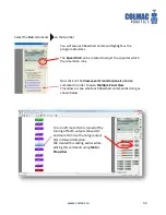
In order to calibrate the LDRs while this LED is on we will use the
Debug Live
command.
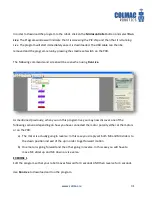
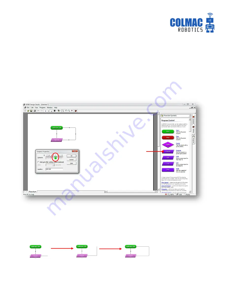
Construct and edit the following ‘Calibrate LDR’ flowchart.
To create the loop, firstly left click and hold the mouse over the right connection point on the
Outputs symbol. Drag the connecting line to the right and then upwards to create the first 90˚bend.
To create the second 90˚bend, release the left mouse button and then click again at a point
approximately in line with the Start command. Continue dragging the line to complete loop.
The Outputs command is
used to turn on the LED
connected to output Q3.
The loop back to the Start
keeps the LED tuned on.
Release and
click again here
Shows the LDRs connected to
A0 and A1 and their current
reading.
Move the robot around and
observe the reading change as
LDRs pass over bright and dark
surfaces.
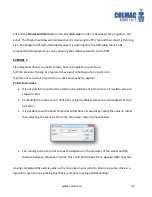
The Outputs command is
used to turn on the LED
connected to output Q3.
The loop back to the Start
keeps the LED tuned on.


