PSoC Analog Coprocessor Pioneer Kit Guide, Doc. # 002-11190 Rev. *B
27
Kit Operation
3.1.2.3
Interfacing with a Thermistor
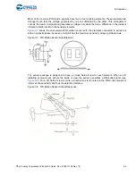
Temperature can be calculated by measuring the thermistor resistance. The PSoC Creator Thermis-
tor Calculator Component simplifies the math-intensive resistance-to-temperature conversion.
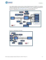
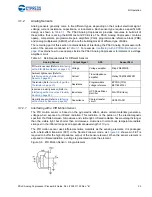
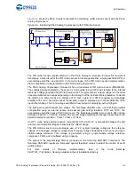
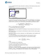
shows the PSoC Creator schematic for interfacing a thermistor with the PSoC Analog
Coprocessor.
Figure 3-11. Interfacing PSoC Analog Coprocessor with a Thermistor
The PSoC Analog Coprocessor Pioneer Kit has a thermistor RT1 (B57164K103J). A 10-k
Ω
reference resistor, R89 (R
ref
), is connected in series with the thermistor.
The thermistor and R
ref
are excited using a 1.2-V bandgap voltage used as a reference voltage. The
bandgap voltage is independent of supply voltage fluctuations and hence provides a stable voltage
reference. This voltage is generated using the programmable reference Component, PVref, and is
buffered using an opamp. The same bandgap voltage is used as the ADC reference. This enables
measurement in the full-scale range of the ADC and results in increased resolution of voltage
measurement.
Three voltage signals (V
therm
, V
low
, and V
hi
) from the resistor divider are connected to the two
differential channels of the Scanning SAR ADC Component. The thermistor (R
T
) resistance is
calculated from the ADC count using the following equation:
The temperature value is then derived by passing the measured resistance to the Thermistor
Calculator component. The Thermistor Calculator component uses a lookup table method to
calculate the temperature with a resolution of 0.1 °C.
For details of firmware implementation, refer to the Code Example
CE211321_Temperature_Sensing
available in the kit installation directory.


