30
XCHARGEIN MOBILITY INSTALLATION MANUAL
MN191005EN April 2021 www.eaton.com
00 Title
S3
S2
ON
ON
1
2 3 4 5
6 7
8
9 10
1
2 3 4 5
6 7
8
9 10
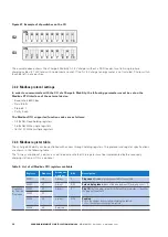
Figure 27. Example of dip switches on the CU
The example above shows the xChargeIn Mobility AC EV charger without a RFID reader, two 16 A single-phase
charging cables (3.7 kW) and with no domestic socket. If the AC EV charger energy meter is not installed, S2 dip switch
8 can be left in any position.
7.2.2 Modbus protocol settings
In order to communicate with the CU of xChargeIn Mobility, the following parameters must be set on the
Modbus RTU interface of the external device:
•
Baud rate: 38400 bps
•
Data: 8 bits
•
Stop bit: 1
•
Parity: Even
The Modbus RTU supported function codes are as follows:
•
03 (0x03): Read holding registers
•
06 (0x06): Write single registers
•
16 (0x10): Write multiple registers
7.2.3 Modbus register table
The xChargeIn Mobility can be controlled with access through holding registers. The protocol and register specifications
are shown in the following table.
The “Always or optional” column is used to indicate whether the register must be implemented by the secondary
charging station, or if this is optional.
Table 9. List of all Modbus RTU registers available
Register
Address
Always or
optional
R/W
Description
40001
00
Always
R
Plug count:
Number of plugs connected to the controller
40002
01
Always
R/W
Selected plug index:
Index of the plug between [0] and [plug count – 1]
Controlled
by Selected
Plug Index
40003
02
Always
R
Plug ID:
ID of the plug – plug ID is different from plug index; it identifies
the plug on the network
40004
03
40005
04
Always
R/W
Enabled
:
0 = No, the charger does not allow charging the vehicle
1 = Yes, the charger can charge the vehicle
40006
05
Reserved


