Modbus Registers
Eaton Power Xpert Gateway PXGX PDP Card User’s Guide 164202122—Rev 1
62
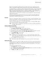
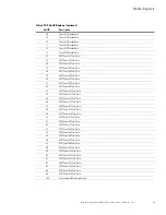
The PDP returns a single register that is a BOOL value (0 or 1), indicating if the alarm is active or not active.
Panel Registers and Alarms
This section contains information for the Panel Summary Registers (FC 04) and the Panel Alarms (FC 02).
Panel Summary Registers (FC 04)
Note:
The panel can be wired for either a wye (phase to neutral) or a delta (phase-to-phase) configuration.
The registers contain only the data supported by the wired configuration. For example, if the panel is
wired in a wye configuration, the voltages AN, BN, and CN are available, but the voltages AB, BC, and
CA are not available (an exception code is returned). Refer to the actual panel for the wiring
configuration.
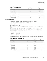
Table 9 shows the registers that contain summary data for the panel. The registers contain the total
information for all the breakers in the panel.
For example, the AC Voltage between Phase A and Neutral is available in register 4010. To read the AC Voltage
in Phase A at Panel #1, set the Modbus program to Unit ID 2 and register 4010:
IP: <IP address of PDP>
Unit ID: 2
Starting Register: 4010
Number of Registers: 2
Function Code: 04
To read the AC Voltage in Phase A at Panel #4, set the Modbus program to Unit ID 5 and register 4010:
IP: <IP address of PDP>
Unit ID: 5
Starting Register: 4010
Number of Registers: 2
Function Code: 04
Table 8. PDP Sample Alarms (FC 02)
Name
Register
Data Type
AC Input Over Volts
1006
BOOL
AC Input Under Volts
1007
BOOL
Input Frequency Fault
1008
BOOL
AC Output Over Volts
1009
BOOL
AC Output Under Volts
1010
BOOL
AC Output Frequency Fault
1011
BOOL
Remote EPO
1012
BOOL
Building Alarm 4
1016
BOOL
Building Alarm 3
1017
BOOL
Building Alarm 2
1018
BOOL
Building Alarm 1
1019
BOOL
Output Overload
1025
BOOL
System Bus Overload
1050
BOOL
NV Memory Failure
1053
BOOL


