background image

CDSA User Manual 

Appendix 


The following technical notes are provided for informational purposes, and are for use by 
authorized personnel only. 

 
A: Serial Remote Control (RS-232) 


The CDSA is equipped with a 9-pin RS232 connector for system remote control via a 
serial cable (not provided by EMM Labs). The cable should be non-crossed for 
connections between a PC and the CDSA. The parameters and settings for this link are: 
 

 19,200 

baud 

 8 

bits 

  1 stop bit 

  no flow control 

  no parity bit 


Commands to CDSA 

 
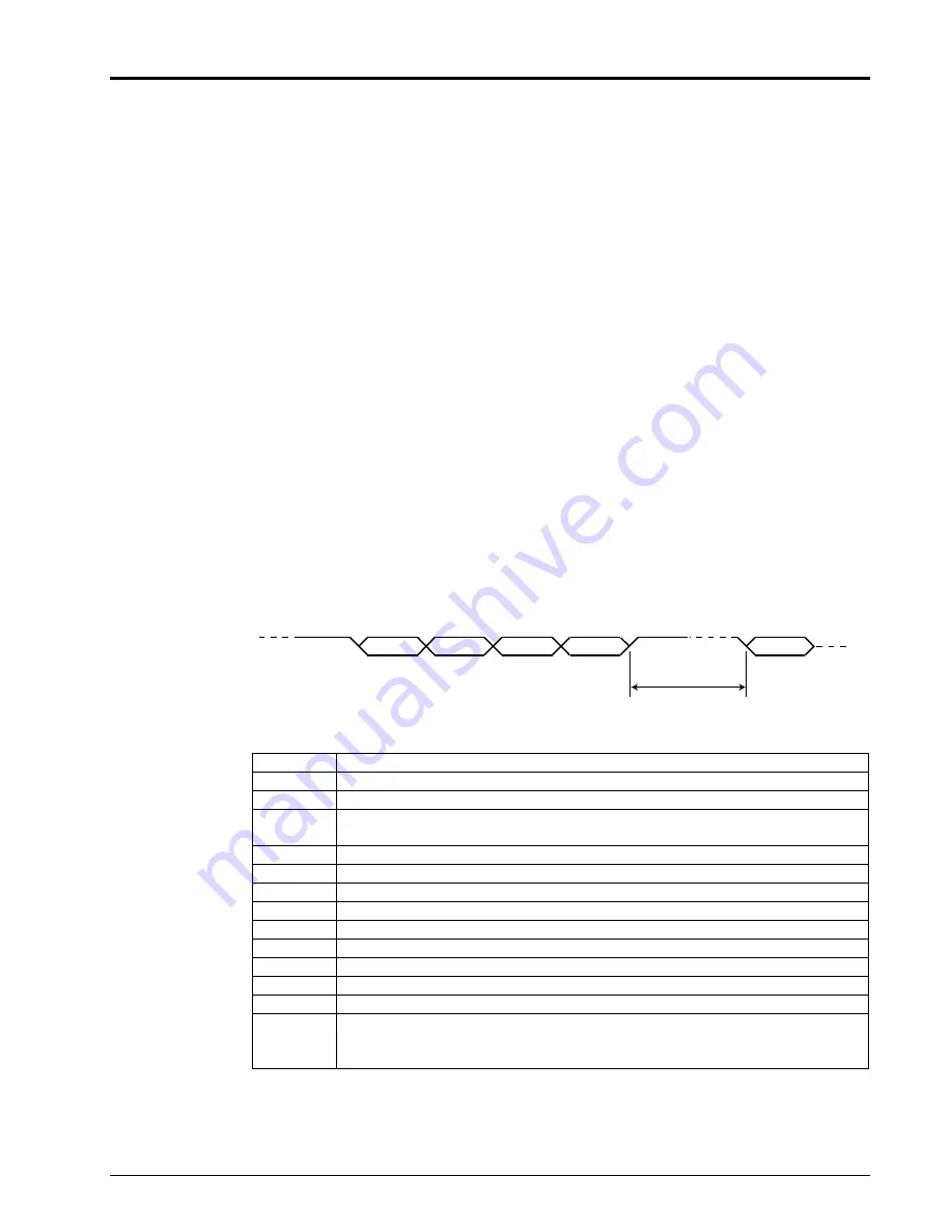
All commands sent to the CDSA consist of 3 ASCII characters followed by a <CR>. 
Repeating  a <CR> will repeat the last command sent. Received commands are not 
stored in a stack and, therefore, need to be sent in intervals of at least 500ms to allow 
enough time for the CDSA to execute a command before receiving the next one. 


Char 0

Char 1

Char 2

<CR>

Char 0

>500ms


ply Start 

playback 

pse Pause 

playback 

stp Stop 

playback 

mod 

Switches between CD and SA-CD stereo layers of a SA-CD disc. The 
player needs to be in stop mode before the layers can be switched. 

rpt 

Toggles between no repeat – repeat track – repeat all 

prv 

Jumps back one track 

nxt 

Jumps to next track 

try 

Opens / closes tray 

don 

Turns front panel display on 

dof 

Turns front panel display off (unit keeps operating) 

pon 

Turns CDSA on from Standby mode 

pof 

Stops playback and sets CDSA to standby 

pol 

Toggles polarity of analog and digital outputs 

tr0, tr1, ..  Direct access to tracks on disc. Track number above 10 can be accessed 

by first sending a command with the tens, and then a command with the 
ones. 


Summary of Contents for CDSA DISC PLAYER

Page 1: ...CDSA DISC PLAYER USER MANUAL Version 1 1...

Page 2: ...eriod of time specified by the product s serial number from the date of first delivery to the owner The warranty time period is 1 year for the drive unit and 5 years for all other parts and is limited...

Page 3: ...ctable levels Low position XLR outputs 4V 14 38dBu RCA outputs 2V 8 353dBu High position XLR outputs 7 2V 19 38dBu RCA outputs 3 6V 13 34dBu Note XLR outputs are balanced with pin 2 hot pin 3 cold and...

Page 4: ...CDSA User Manual 4...

Page 5: ...ERT Inverts polarity absolute phase of analog and digital outputs The inversion is done in the digital domain PLAY Starts playback or continues it from Pause mode PAUSE Pauses playback press PLAY to c...

Page 6: ...n leading zeros as appropriate after a timeout period The user may experience a short delay without sending any leading zeros MODE This provides the same functionality as the button on the front panel...

Page 7: ...erefore need to be sent in intervals of at least 500ms to allow enough time for the CDSA to execute a command before receiving the next one Char 0 Char 1 Char 2 CR Char 0 500ms ply Start playback pse...

Page 8: ...Reading indicator is on front panel bit 1 1 when Repeat Track indicator is on front panel bit 2 1 when Repeat All indicator is on front panel bit 3 1 when CD PCM 2HC indicator is on front panel bit 4...

Page 9: ...will connect your CDSA via its USB connector to a PC First Time Installation and Upgrade Procedure 1 Do not connect the CDSA yet to the PC 2 Launch the supplied application emmsetup exe on your PC and...

Page 10: ...Proceed from here as for first time installation IMPORTANT NOTE THE ENTIRE UPDATE PROCEDURE CAN TAKE UP TO 1 MINUTE IT IS IMPORTANT THAT YOU DO NOT INTERRUPT POWER TO THE CDSA NOR DISCONNECT THE USB C...

Reviews: