EMTRON ELC USER MANUAL
WWW.EMTRON.WORLD
© EMTRON AUSTRALIA PTY LTD MARCH 2018
24
Appendices
Appendix 1
–
CAN Bus Data Packaging
This section outlines the CAN Protocol used to communicate with the ELC device(s). If the
device is connected to an Emtron ECU, the CAN Bus packet is automatically decoded when
CAN ELC Dataset is selected and no additional setup is required. For more information refer
to Section
7.
0.
This section provides more detailed information on the CAN ID data structure and requires
an understanding of both CAN protocols and data packaging.
Baud Rate
The device will Auto-scan the CAN bus until a successful baud rate has been detected. Once
detected this rate will be stored by the device and used at the next power up.
The device will scan 3 different Baud rates at 500ms intervals moving from 1Mbaud ->
500kBaud -> 250k Baud -> 1Mbaud and so on.
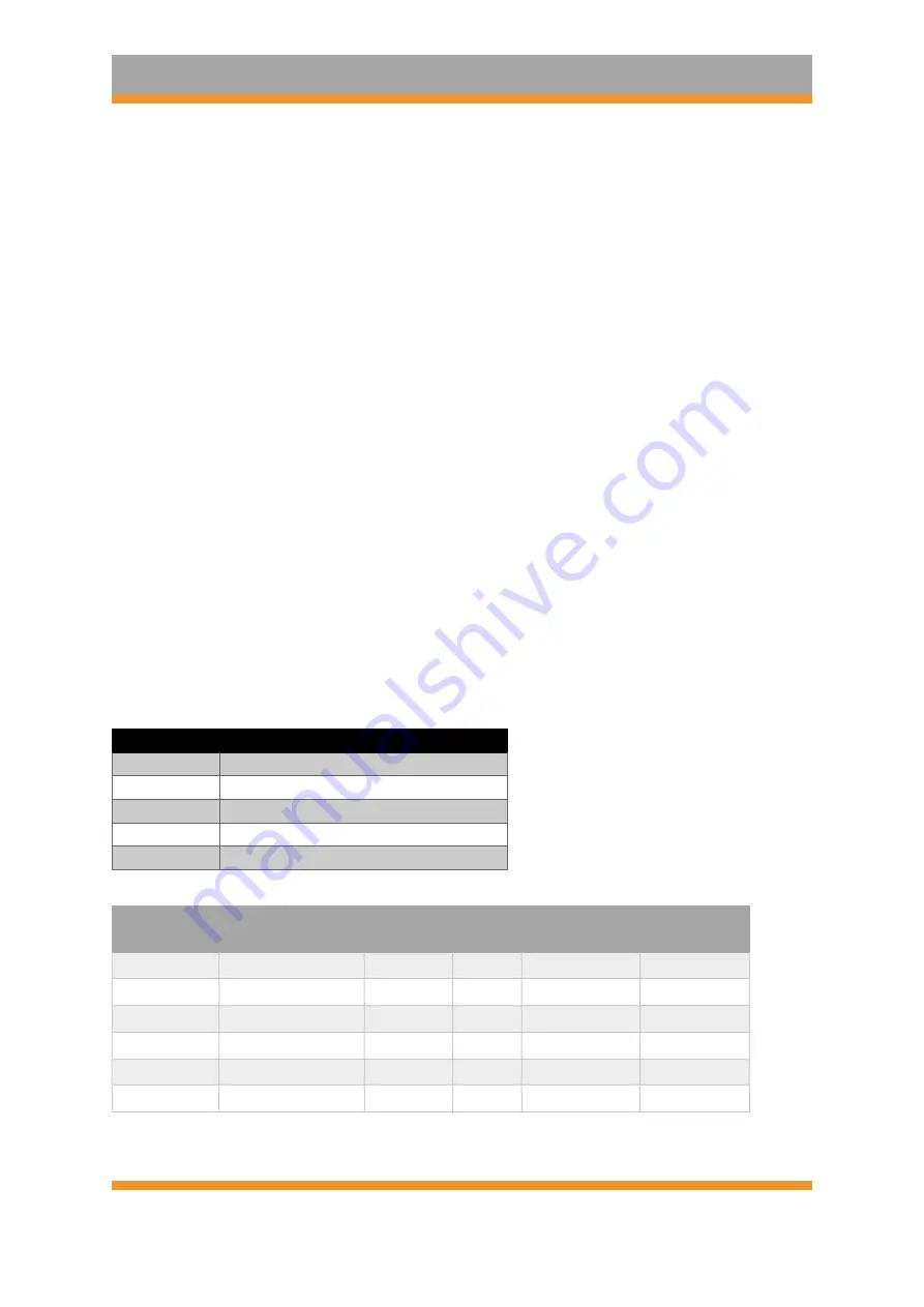
ELC CAN Data Format
ID
671 /0x28F (Default)
Data
Lambda Channel 1
ID Type
Standard 11-bit identifier
Direction
Transmit from Device
Length
8 bytes
Tx Rate
100Hz/10ms
CAN ID
Name
Start bit
Length
(bits)
Byte Order
Data Type
671/0x28F
Index = 0
0
8
Little Endian
Unsigned
Lambda 1
8
16
Little Endian
Unsigned
Pump Current 1
24
16
Little Endian
Signed
Fault 1
40
8
Little Endian
Unsigned
Status 1
48
8
Little Endian
Unsigned
Heater 1 DC
56
8
Little Endian
Unsigned


