background image

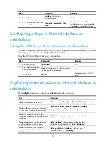
Step Command 

Remarks 

3.


Set the statistics polling 

interval. 

flow-interval 

interval


The default setting is 300 seconds. 


To display the interface statistics collected in the last polling interval, use the 

display interface

 command.  

To clear interface statistics, use the 

reset counters interface

 command. 

Configuring a Layer 2 Ethernet interface  

Configuring storm suppression 

You can use the storm suppression function to limit the size of a particular type of traffic (broadcast, 

multicast, or unknown unicast traffic) on an interface. When the broadcast, multicast, or unknown unicast 

traffic on the interface exceeds this threshold, the system discards packets until the traffic drops below this 
threshold.  

Configuration guidelines 


When you configure the suppression threshold in pps or kbps, the device converts the configured 

value into a multiple of a certain step (6400 for 

pps

 and 50 for 

kbps

) supported by the chip. As a 

result, the actual suppression threshold may be different from the configured one. For the 
suppression threshold that takes effect, see the prompt on the device.  


On an interface, you can configure only one of the 

kbps

 and 

pps

 keywords. To switch between the 

kbps

 and 

pps

 keywords, you must first restore the broadcast, multicast, or unknown unicast 

suppression threshold to the default.  


On an interface, only one suppression threshold is supported for different types of traffic. For 
example, if you have configured the broadcast suppression threshold as 100 kbps by using the 

broadcast-suppression kbps


100

 command on an interface, to configure the multicast suppression 

threshold and unknown unicast threshold on the interface, you can only use the 

multicast-suppression kbps


100

 and 

unicast-suppression kbps 100

 commands.  

Configuration procedure 

To set storm suppression thresholds on one or multiple Ethernet interfaces: 


Step Command 

Remarks 

1.


Enter system view. 

system-view 

N/A 

2.


Enter Ethernet interface view. 

interface 

interface-type 

interface-number


N/A 

3.


Enable broadcast suppression 
and set the broadcast 

suppression threshold. 

broadcast-suppression 

ratio 

|


pps

 max-pps

 | 

kbps 

max-kbps

 } 

By default, broadcast traffic is 
allowed to pass through an 

interface. 
The 

ratio

 argument is always 100.  

4.


Enable multicast suppression 
and set the multicast 

suppression threshold. 

multicast-suppression 

ratio 

|


pps


max-pps

 | 

kbps 

max-kbps

 } 

By default, multicast traffic is 
allowed to pass through an 

interface. 
The 

ratio

 argument is always 100.  

Summary of Contents for S12500 Series

Page 1: ...H3C S12500 Series Routing Switches Interface Configuration Guide Hangzhou H3C Technologies Co Ltd http www h3c com Software version S12500 CMW710 R7128 Document version 6W710 20121130...

Page 2: ...ware Secware Storware NQA VVG V2 G Vn G PSPT XGbus N Bus TiGem InnoVision and HUASAN are trademarks of Hangzhou H3C Technologies Co Ltd All other trademarks that may be mentioned in this manual are th...

Page 3: ...onventions This section describes the conventions used in this documentation set Command conventions Convention Description Boldface Bold text represents commands and keywords that you enter literally...

Page 4: ...formation NOTE An alert that contains additional or supplementary information TIP An alert that provides helpful information Network topology icons Represents a generic network device such as a router...

Page 5: ...software features and configuration procedures Command references Provide a quick reference to all available commands Operations and maintenance System log messages Explains the system log messages Tr...

Page 6: ...http www h3c com Documentation feedback You can e mail your comments about product documentation to info h3c com We appreciate your comments...

Page 7: ...et interface 6 Setting the statistics polling interval 6 Configuring a Layer 2 Ethernet interface 7 Configuring storm suppression 7 Forcibly bringing up a fiber GE or 10 GE port 8 Setting the MDIX mod...

Page 8: ...rnet subinterface By creating subinterfaces on a Layer 3 Ethernet interface you enable the interface to carry packets for multiple VLANs Configuring common Ethernet interface settings IMPORTANT By def...

Page 9: ...ccess point identifier The sending end keeps the connection with the receiving end by sending this byte repeatedly The Path Trace byte J1 a byte in the High Order Path Overhead usually serves as a hig...

Page 10: ...down Configuring an Ethernet subinterface Step Command Remarks 1 Enter system view system view N A 2 Create an Ethernet subinterface interface interface type interface number subnumber N A 3 Set the i...

Page 11: ...nterface type interface number N A 3 Configure jumbo frame support jumboframe enable value By default the device allows jumbo frames within 9216 bytes to pass through On LST1XP16LEB1 and LST1XP16LEC1...

Page 12: ...With this command configured when the interface comes down or goes up the link updown event is not reported to the CPU until the interface is still down or up when the suppression interval delay time...

Page 13: ...drops on a link you can enable generic flow control at both ends of the link When traffic congestion occurs at the receiving end the receiving end sends a flow control Pause frame to ask the sending...

Page 14: ...one of the kbps and pps keywords To switch between the kbps and pps keywords you must first restore the broadcast multicast or unknown unicast suppression threshold to the default On an interface only...

Page 15: ...able a fiber port to forward traffic over a single link you can use the port up mode command This command brings up a fiber port by force even when no fiber links or optical modules are present If one...

Page 16: ...s each of which plays a dedicated role For example pins 1 and 2 transmit signals and pins 3 and 6 receive signals You can use both crossover and straight through Ethernet cables to connect copper Ethe...

Page 17: ...efault setting is 1500 bytes Displaying and maintaining an Ethernet interface or subinterface Execute display commands in any view and reset commands in user view Task Command Display interface traffi...

Page 18: ...r subinterface statistics reset counters interface interface type interface number interface number subnumber Clear the statistics of dropped packets on the specified interfaces reset packet drop inte...

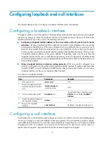
Page 19: ...evice does not forward these packets Using a loopback interface in dynamic routing protocols With no router ID configured for a dynamic routing protocol the system selects highest loopback interface I...

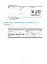
Page 20: ...rface 4 Restore the default settings for the null interface default N A Displaying and maintaining loopback and null interfaces Execute display commands in any view and reset commands in user view Tas...

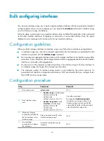
Page 21: ...aggregate interface and its member interfaces can break up the aggregation No limit is set on the maximum number of interfaces in an interface range The more interfaces in an interface range the longe...

Page 22: ...15 Step Command Remarks 5 Optional Verify the configuration display this N A...

Page 23: ...Layer 3 Ethernet interface or subinterface 61H10 Configuring a loopback interface 62H12 Configuring a null interface 63H12 Configuring common Ethernet interface settings 64H1 D Displaying and maintai...

Reviews: