6.
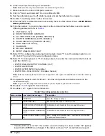
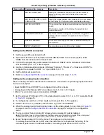
Type the number “7” to start the calibration mode. Calibration data and two instruction lines show
on the monitor.
• SPACE—toggles analog outputs between 4 mA and 20 mA
• RETURN—goes back to the main menu
7.
Push the space bar once to start the system (current flow).
8.
Push the space bar to toggle from 4 mA to 20 mA or from 20 mA to 4 mA current source as read
on the ammeter.
Push the space bar again to toggle back and forth.
9.
When done, push <Enter> to return to the main menu.
Note: Failure to enter the "quit" command can result in erroneous calibration and address values.
10.
To stop the sequence, type “Q <Enter>”.
11.
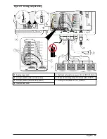
Set the power of the instrument to off and remove the programming cable and the ammeter.
12.
Return all wiring to the original configuration. Refer to
Electrical installation
on page 12.
PC communications
Install the data collection software on the computer. Refer to the software documentation for more
information. The software controls the instrument operation and saves the count data to the
computer memory.
Communications protocol
The instrument has four serial communications settings:
• Eight data bits
• No parity
• 9600 baud (RS232)
• One stop bit
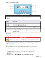
Use the computer to change the device select mode [= 128 (ID# = 00)]. Refer to
Configuration
on page 19 to change the value.
Command syntax
The instrument responds to ASCII commands and sends a data record that changes in length related
to the content.
The instrument gives results to all commands and selected codes when the command character is
sent back to the computer. If the instrument does not identify a command, it sends a “?” character. If
the computer asks for a record from an empty buffer, the instrument sends a “#” character. If the
computer asks for a record that is already sent the instrument sends a “#” character unless the
computer uses the Resend Record command. The instrument does not send any command
characters if a parity or framing error occurs.
The command and data syntax is specified in
Table 6
.
Note: The ASCII commands that are used by the instrument are case sensitive.
Table 6 ASCII commands
Command
Description
“c” start counting
(computer controlled)
The counter starts to count and does not wait for a second boundary (quick start).
The count will continue until it is stopped by the computer. The count cycle must be
controlled by the computer.
“d” start counting (counter
controlled)
The counter starts to count and control the count cycle based on the front-panel
setting for period (sample time).
“e” stop counting
The counter stops counting immediately and does not wait for a second boundary.
“o” alarm output
The analog multiplexer sets (or resets) a current-sinking output for an external alarm
activation or deactivation.
“C” clear buffer
The rotating buffer is erased.
24
English


