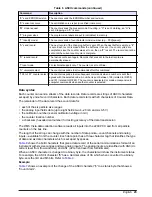
Table 6 ASCII commands (continued)
Command
Description
“E” send EPROM revision
The counter sends the EPROM number and revision.
“K” sensor cal curve
The calibration curve is put (or verified) in memory.
“M” mode request
The counter sends the present mode: Counting, a “C” is sent. Holding, an “H” is
sent. Stopping, an “S” is sent.
“P” program sizes
The program size labels are put (or validated) in memory.
“T” identify model
The counter sends a four-character model number (e.g., PCX[space]).
“A” send record
The next record of the changing buffer is sent. When the next buffer is empty, a “#”
is sent. Each record is erased from the buffer as it is sent. If no count cycles are
completed, since the counter was set to on, then a “#” is sent. The record cannot be
sent until the current count cycle is complete.
“R” resend record
The last record is sent again. Records that are sent to the last record are
permanently erased.
“l” local mode
For technical support only. The counter is set to off-line.
“U” universal select
The counter responds to all commands after this command.
“128 to 191” counter select The counter responds to all subsequent commands when a number is sent that
agrees with the selected code. A number is sent between 128 (related to ID# 00)
and 191 (related to ID# 63). The counter is deselected, or made unresponsive to
computer commands when another counter is selected.
Data syntax
Each counter can send a stream of the data records. Data records are strings of ASCII characters
set apart by end-of-record characters. Each data record starts with 20 characters of Counter Data.
The remainder of the data record has count data for:
• each of the six particle size ranges
• the analog input fields data (up to eight fields: two 4–20 mA and six 0-5 V)
• the calibration number (sensor calibration voltage in mV)
• the counter location number
• a checksum (hexadecimal number) for testing accuracy of the data transmission
The WQS Vista data collection software reads all inputs into the 2200 PCX and from all particle
counters on the bus line.
The length of the string can change with the number of data points—count channels and analog
inputs—available from the counter. Each data point has a three-character tag that identifies the type
of data and six data characters which is set apart by spaces.
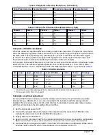
Table 8
shows the bold characters that give a data record of the serial communications format of an
instrument with six size ranges and two analog inputs. The analog inputs are identified with AN0 (dc
current level from flow controller) and AN1 (dc current level from turbidimeter).
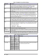
When an ASCII character is changed to a binary byte, the character will show the instrument status.
For example, the ASCII character “$” has a decimal value of 36, which when converted to a binary
byte, sets the 3rd and 6th bits. Refer to
Table 9
.
Example:
Table 7
shows an example of the change of the ASCII character “$” to a status byte that shows a
“Count Alarm”.
English
25


