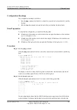
Configuration Roadmap
The configuration roadmap is as follows:
1.
Run the
ping
command on Switch A to check the connectivity between Switch A and the
log host.
2.
Run the
tracert
command to locate the fault after you find that the link is faulty.
Data Preparation
To complete the configuration, you need the following data:
l
IP addresses of the interfaces on Switch B (In this example, IP addresses of the interfaces
are 1.1.1.2/8 and 2.1.1.1/8.)
l
IP addresses of the interfaces on Router (In this example, IP addresses of the interfaces are
2.1.1.2/8 and 3.1.1.1/8.)
l
IP address of the log host (In this example, the IP address of the log host is 3.1.1.2/8.)
Procedure
Step 1
Run the
ping
command.
# Run the
ping
command on Switch A to check the connectivity between Switch A and the log
host.
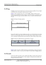
<Quidway>
ping 3.1.1.2
PING 3.1.1.2: 56 data bytes, press CTRL_C to break
Request time out
Request time out
Request time out
Request time out
Request time out
--- 3.1.1.2 ping statistics ---
5 packet(s) transmitted
0 packet(s) received
100.00% packet loss
The display on Switch A shows that the log host is unreachable, which indicates that a fault
occurs on some link segment between Switch A and the log host.
Step 2
Run the
tracert
command.
# Run the
tracert
command on Switch A to locate which link segment fails.
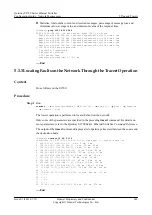
<Quidway>
tracert 3.1.1.2
traceroute to 3.1.1.2(3.1.1.2), max hops: 30 ,packet length: 40
1 1.1.1.2 4 ms 5 ms 5 ms
2 * * *
3 * * *
4 * * *
5 * * *
6 * * *
7 * * *
8 * * *
...
The preceding display shows that the ICMP Echo Request message passes Switch B but does
not reach Router. It indicates that the link between Switch B and Router fails. After the link
Quidway S2700 Series Ethernet Switches
Configuration Guide - Network Management
5 Ping and Tracert
Issue 01 (2011-07-15)
Huawei Proprietary and Confidential
Copyright © Huawei Technologies Co., Ltd.
251


