1.
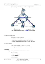
Add the physical interfaces of SwitchA and SwitchB to the Eth-Trunk.
2.
Enable global LLDP on SwitchA and SwitchB.
3.
Enable SwitchA and SwitchB to process LLDP BPDUs.
4.
Configure management addresses for SwitchA and SwitchB.
Data Preparation
To complete the configuration, you need the following data:
l
Management address 10.10.10.1 for SwitchA and management address 10.10.10.2 for
SwitchB
l
Number of the Eth-Trunk between SwitchA and SwitchB, and numbers of the interfaces
added to the Eth-Trunk
Procedure
Step 1
Configure the Eth-Trunk between SwitchA and SwitchB.
# Configure SwitchA.
<Quidway>
system-view
[Quidway]
sysname SwitchA
[SwitchA]
vlan batch 100
[SwitchA]
interface eth-trunk 1
[SwitchA-Eth-Trunk1]
trunkport ethernet 0/0/1
[SwitchA-Eth-Trunk1]
trunkport ethernet 0/0/2
[SwitchA-Eth-Trunk1]
trunkport ethernet 0/0/3
[SwitchA-Eth-Trunk1]
port link-type trunk
[SwitchA-Eth-Trunk1]
port trunk allow-pass vlan 100
[SwitchA-Eth-Trunk1]
quit
# Configure SwitchB.
Same as the configurations on SwitchA.
Step 2
Enable global LLDP on SwitchA and SwitchB.
# Configure SwitchA.
[SwitchA]
lldp enable
# Configure SwitchB.
Same as the configurations on SwitchA.
Step 3
Enable SwitchA and SwitchB to process LLDP BPDUs.
# Configure SwitchA.
[SwitchA]
bpdu enable
# Configure SwitchB.
Same as the configurations on SwitchA.
Step 4
Configure management addresses for SwitchA and SwitchB.
# Configure SwitchA.
[SwitchA]
lldp management-address 10.10.10.1
# Configure SwitchB.
Quidway S2700 Series Ethernet Switches
Configuration Guide - Network Management
2 LLDP Configuration
Issue 01 (2011-07-15)
Huawei Proprietary and Confidential
Copyright © Huawei Technologies Co., Ltd.
73


