User Guide
13 of 32
002-29388 Rev. *B
2022-06-15
EZ-
PD™ BCR HPI Utility user guide
EZ-
PD™ BCR HPI Utility
2.5.3
GPIO
The BCR device has a GPIO called “GPIO_1” that is assigned to Pin 8
of the BCR device; it is associated with pin 4
of J1 connector of the CY4533 EZ-
PD™ BCR EVK
board. It can be configured by the host processor to allow
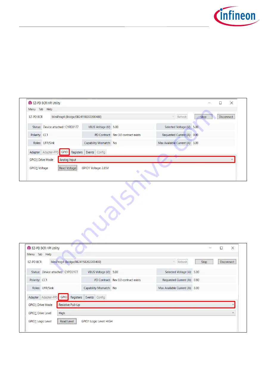
control of some circuitry (i.e., LED control). The GPIO tab in the GUI demonstrates the different drive modes and
control options for that GPIO. Note that only the CYPD3177 BCR device provides GPIO feature. If you use
CYPD3176 or CYPD3178 device, the GPIO tab is automatically disabled.
You can also refer to the
for details on GPIO_1.
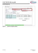
Figure 16
GPIO tab
–
Analog input
From
GPIO1 Drive Mode
, you can select the drive mode. See SET_GPIO_MODE in the BCR HPI specification.
When you select the
Analog Input
option, you can read the GPIO_1 voltage level. See SAMPLE_GPIO register in
the BCR HPI specification.
Once you select other digital drive modes, the GUI provides additional options to set and the logic status. See
READ_GPIO_LEVEL and SET_GPIO_LEVEL in the BCR HPI specification.
Figure 17
GPIO tab
–
Resistive pull-up


