42
Chapter 6
– Commissioning
XtrapulsCD1-a
3.8 - APPLICATION OF THE STEPPER MOTOR EMULATION
The stepper motor emulation is only possible on motors equipped with a resolver. The
Pulse
and
Direction
signals are received via the input of the second drive position sensor, on the TTL encoder input pins.
- Select
Stepper emulation
in the
Position sensor configuration
window.
- Launch the
Autotuning
procedure by selecting the
Position
mode.
Note: The position loop stability can be tested with the
PI
2
speed mode because the
Feedback
gains are identical
to the
Position
mode.
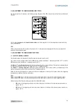
- Enter the value of the
Position resolution
parameter in the
Scaling
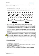
window as shown below:
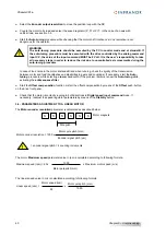
Position resolution
= 2 x number of pulses issued by the controller for one motor revolution
- Set at 0 the value of the
Position deadband
parameter. This parameter is only useful for applications with high
transmission backlashes or with high axis frictions. In those cases, when the position error value at standstill is
lower than the
Position deadband
parameter value, the proportional gain of the position loop is set at 0.
- Enable the drive and check the axis displacement during the execution of the controller program.
- If the axis does not move, check that the
CV0
input is disabled.
- If there is a loud noise in the motor during the axis displacement, the
Feedforward acceleration
gain must be
set at 0.
- If the motor is moving in the wrong direction, select the
Reverse movement
command in the
Speed limit
window.
3.9 - SOFTWARE GEARING APPLICATION
The software gearing application requires the use of the drive second position sensor for measuring the
displacements of the master axis.
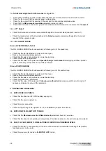
- If the motor is equipped with a resolver, select the encoder type for the input of the second sensor in the
Encoder input configuration
part of the
Position sensor configuration
window.
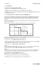
- When using a master SinCos encoder, adjust the
Position scaling factor
parameter in the
Second sensor
window for increasing the resolution of the position measurement. Otherwise, set at 1 the value of the
Position
scaling factor
parameter.
- Execute the
Autotuning
command by selecting the
Position
mode.
Note: The position loop stability can be tested in
PI²
speed mode because the
Feedback
gains are identical to the
Position
mode.
-
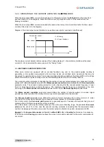
When using a master encoder, enter the value of the
Position resolution
parameter in the
Scaling
window, as
described below:
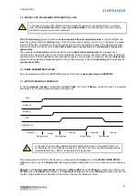
Position resolution
= (4 x number of encoder pulses/channel for one axis revolution of the master encoder x
Position scaling factor
) / reduction ratio.
Reduction ratio = Motor speed / Master encoder speed
-
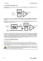
When using a master resolver, enter the value of the
Position resolution
parameter in the
Scaling
window, as
described below:
Position resolution
= (65536 x
Position scaling factor
) / Reduction ratio
Reduction ratio = Motor speed / Master resolver speed
- Set at 0 the value of the
Position deadband
parameter. This parameter is only useful in applications with high
transmission backlashes or applications with hig axis frictions. In those cases, when the position error value at
standstill is lower than the value of the
Position deadband
parameter, the proportional gain of the position loop
is set at 0.

