S p e z i a l e l e k t r o n i k G m b H
iseg
c/o ROTECH
Email: sales@iseg-hv.de
Phone ++ 49 351 / 26 95 - 260
Spezialelektronik
Bautzner Landstr. 45
http://www.iseg-hv.com
Fax
++ 49 351 / 26 95 - 261
GmbH
D - 01454 Rossendorf
Germany
5
4. Communication via interface
4.1 Device Control Protocol DCP
The communication between the controller and the module works according to the Device Control
Protocol DCP, which has been designed for the use of multi-level-hierarchy systems for instruments.
This protocol is working according to the master slave principle. Therefore, the controllers which are
on higher hierarchy are working as masters always while devices, which are on lower hierarchy are
working as slaves.
In the event of the control of the HV device through a controller the controller will have the master
function in this system, while the module (as a Front-end device with intelligence) will be the slave.
The data exchange between the controller and the Front-end (FE) device works with help of data
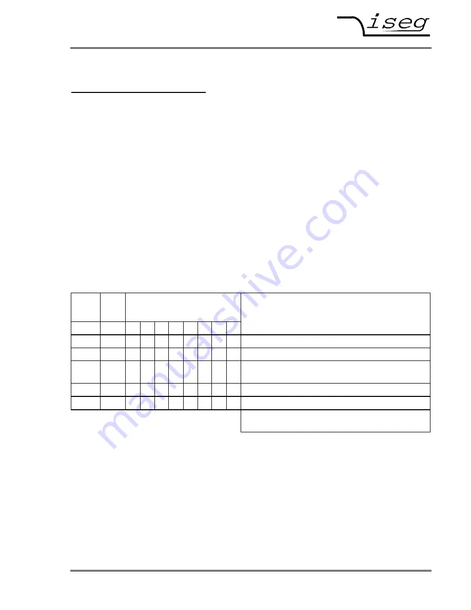
frames. These data frames are assembled of one direction bit DATA_DIR, one identifier bit
DATA_ID and further data bytes. The direction bit DATA_DIR defines whether the data frame is a
write or read-write access. The DATA_ID carries the information of the type of the data frame and
occasionally sub addresses (G0, G1). It is characterised through the first byte of the data frame with
bit 7=1. The function of the module as part of a complex system will be defined through the
DATA_ID .
In such systems with many hierarchical levels a single function of a single module can be addressed
by using group controllers (GC). Then, for each GC on the way to the module the data frame is
created through nesting of the address fields of the GC-addresses followed by the DATA_ID (not
necessary in case of control a single module).
EXT_
INSTR
DATA
_DIR
DATA_ID
Bit
Access
7
6
5
4
3
2
1
0
x
0
x
x
x
x
x
x
x
No
DATA_ID
0/1
0
1
0
x
x
x
x
x
x
Write access
on Front-end device
0/1
1
1
0
x
x
x
x
x
x
Read-write access
on Front-end device
(Request at Write)
0/1
0
1
1
x
x
x
x
G1 G0
Write access
on group
0/1
1
1
1
x
x
x
x
G1 G0
Read-write access
on group (Request at Write)
G0, G1 sub address
Only needed if group controller (GC) is used
These data frames correspond to a transfer into layer 3 (Network Layer) respectively layer 4
(Transport Layer) of the OSI model of ISO. The transmission medium is CAN Bus according to
specification 2.0A, related to level1 (Physical Layer) and level 2 (Data Link Layer).
The Device Control Protocol DCP has been matched to the CAN Bus according to specification CAN
2.0A, but it is also possible to be matched to further transmission media (e.g. RS232). Therefore
specials of layer 1 and 2 are only mentioned if absolutely necessary and if misunderstandings of
functions between the Transport Layer and functions of the Data Link Layer may be possible. The
communication between the controller and a module on the same bus segment will be described as
follows.


