LOOPING ENVELOPE (LOOPEG) | 41
GRAPHIC DISPLAY
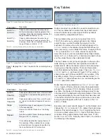
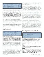
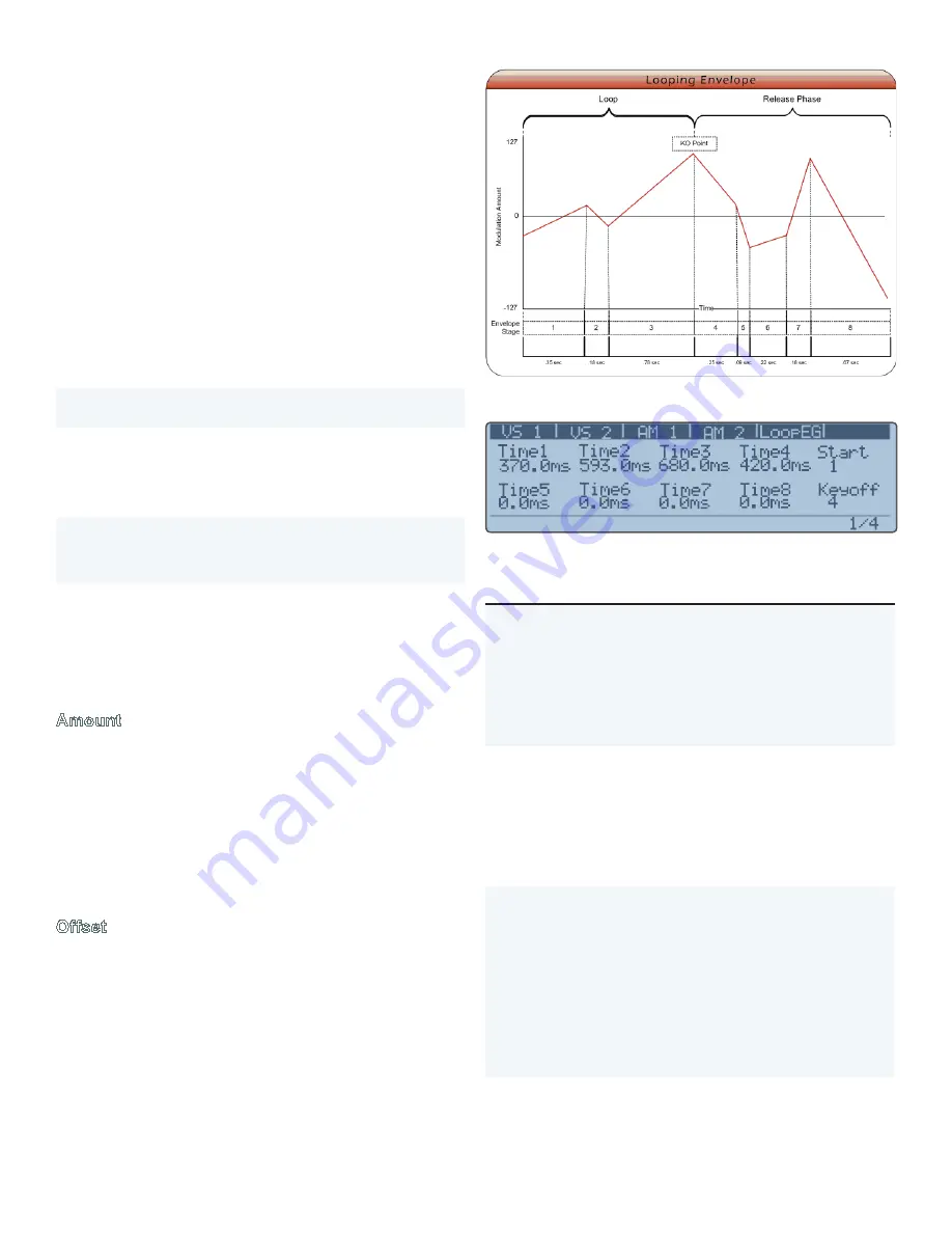
Figure 74. Looping Envelope diagram
Figure 75. Looping Envelope Menu, page 1 of 4
Parameter
Description
Time1 –
Time8
These controls determine the length of each
of the 8 segments of the envelope. The default
range of the time controls is 1.0 ms – 20.0
seconds. The Looping Envelope can also be
synced to the MIDI clock by setting the
Sync
parameter on menu page 4. When synced to
MIDI clock, the time values for each segment
are shown in time divisions.
Start
When Loop is enabled, this control determines
the starting point of the loop. The envelope
will play as normal up until the KeyOff Point,
then loop back to the segment indicated by this
control. The loop will continue until the key is
released, at which point the release phase of
the loop is activated, from KeyOff Point through
segment 8.
KeyOff
This control serves two purposes. When Loop
Mode is active, KeyOff Point determines the last
segment in the loop. KO Point also defines the
beginning of the release stage of the enve-
lope. If Loop Mode is off, segments 1 to KeyOff
Point represent the attack and decay portions
of the envelope. The KeyOff Point represents
the Sustain portion. Segments following the
KeyOff Point represent the release phase of the
envelope. When Loop Mode is on, the envelope
behaves as described above.
Table 14. Looping Envelope Main mode, page 1 parameters
Amplitude Modulation (AM) is a process of varying the
amplitude of one sound (the carrier) by the amplitude of
another (the modulator). If the frequency of the modulator is
sub-audio, AM results in a tremolo effect. If the modulator’s
frequency is above around 10hz, the timbre of the carrier
is affected by the introduction of additional partials to the
output. When two sine waves are used, AM results in two
additional sidebands equally spaced around the carrier’s
fundamental frequency. The frequency of the sidebands is
the sum and difference of the carrier and modulator’s fre-
quencies, and the amplitude of the new partials is half the
amplitude of the carrier.
Solaris has 2 AM modules. Any source can be used as the
carrier or modulator, though a classic AM synthesis tech-
nique is to modulate the amplitude of one oscillator with
another oscillator. The following algorithms are available:
Shift
Typical AM that produces two sidebands around the
carrier
Clip
Multiplies the two input signals and clips the result.
Creates two strong sidebands (stronger than those
generated by Shift) around the carrier’s frequency,
and on strong sideband at a much lower frequency.
Phase cancellation eliminates the original carrier.
Abs
(abso-
lute)
Outputs the absolute value of multiplying the two
input signals without clipping. Creates two weak
sidebands widely spaced around the carrier.
Ring
Classic ring modulation that creates two strong
sidebands around the carrier and eliminates the car-
rier completely due to phase cancellation.
Table 13. AM Algorithms
The AM section can be side chain modulated by selecting a
modulation source for the
Control
parameter.
Amount
This is a bipolar mixer for the output of the algorithm. Using
Ring Mod
as an example: if you have the
Offset
at
0
, the
Amount
will seem just like a bipolar mixer (with negative
values just producing an inverted phase signal), and when
the
Amount
is at 0, you won’t hear anything. However, if
you then adjust the
Offset
to some other value, you will
hear some of the original
Carrier
input, and then by adjust-
ing the
Amount
, you can hear the Ring Modulated output
increase.
Offset
Shifts the
Carrier
input above or below (or around) zero.
Looping Envelope (LoopEG)
The Looping Envelope is a two dimensional, 8-stage bipo-
lar envelope with looping capability. This envelope can be
selected as a modulation source for any other modulation
destination.
Summary of Contents for Solaris
Page 1: ...User Guide Version 1 ...


