93
of velocity loop; otherwise oscillation may occur. The formula for calculating the bandwidth of feedback filter
of velocity loop is F = Speed_Fb_N*20+100 (Hz).
2. Parameters for position loop
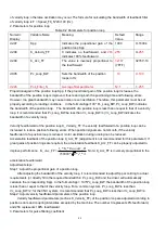
Table 8-2 Parameters for position loop
Numeric
Display
Variable Name
Meaning
Default
Value
Range
d2.07
Kpp
Indicates the proportional gain of the
position loop Kpp
1000
0~16384
d2.08
K_Velocity_FF
0 indicates no feedforward, and
255
indicates 100% feedforward
255
0~
255
d2.09
K_Acc_FF
The value is inversely proportional to
the feedforward
32767
(7FF.F)
32767~10
d0.05
Pc_Loop_BW
Sets the bandwidth of the position
loops in Hz
10
0~100
d2.26
Pos_Filter_N
Average filter parameter
N=1
1~255
Proportional gain of the position loop Kpp: If the proportional gain of the position loop increases, the
bandwidth of the position loop is improved, thus reducing both the positioning time and following errors.
However, too great bandwidth may cause noise or even oscillation. Therefore, this parameter must be set
properly according to loading conditions. In the formula Kpp=103* Pc_Loop_BW, Pc_Loop_BW indicates
the bandwidth of the position loop. The bandwidth of a position loop is less than or equal to that of a velocity
loop. It is recommended that Pc_Loop_BW be less than Vc_Loop_BW /4 (Vc_Loop_BW indicates the
bandwidth of a velocity loop).
Velocity feedforward of the position loop K_Velocity_FF: the velocity feedforward of a position loop can be
increased to reduce position following errors. When position signals are not smooth, if the velocity
feedforward of a position loop is reduced, motor oscillation during running can be reduced.
Acceleration feedback of the position loop K_Acc_FF (adjustment is not recommended for this parameter): If
great gains of position rings are required, the acceleration feedback K_Acc_FF can be properly adjusted to
improve performance.
*
*
_
K_Acc_FF
250000* 2 *
*
p
t
t
I
K
Encoder
R
J
Note: K_Acc_FF is inversely proportional to the
acceleration feedforward.
Adjustment steps:
Step 1: Adjust the proportional gain of a position loop.
After adjusting the bandwidth of the velocity loop, it is recommended to adjust Kpp according to actual
requirements (or directly fill in the required bandwidth in Pc_Loop_BW, and the driver will automatically
calculate the corresponding Kpp). In the formula Kpp = 103*Pc_Loop_BW, the bandwidth of the position loop
is less than or equal to that of the velocity loop. For a common system, Pc_Loop_BW is less than
Vc_Loop_BW /2; for the CNC system, it is recommended that Pc_Loop_BW is less than Vc_Loop_BW /4.
Step 2: Adjust velocity feedforward parameters of the position loop.
Velocity feedforward parameters (such as K_Velocity_FF) of the position loop are adjusted according to
position errors and coupling intensities accepted by the machine. The number 0 represents 0% feedforward,
and 256 represents 100% feedforward.
3. Parameters for pulse filtering coefficient
Summary of Contents for CD2S Series
Page 7: ...7...
Page 8: ...8 1 3 3 Power Brake and Encoder cable of Motors...
Page 12: ...12 Fig 2 3 Installation direction...
Page 15: ...15 3 1 2 Wiring Diagram Fig 3 1 Wiring diagram of CD2S driver...
Page 23: ...23 Fig 4 3 Separate regulation of bits...
Page 82: ...82...
Page 96: ...96 8 4 Debugging example 8 4 1 Oscilloscope 1 Enter oscilloscope 2 Parameters for Oscilloscope...
Page 98: ...98 In Auto Reverse mode Kvp 110...
Page 100: ...100 The oscilloscope is as following max following error is 69 inc Fig 2 Kpp 30 Vff 100...
Page 101: ...101 The oscilloscope is as following max following error is 53 inc Fig 3 Kpp 30 Vff 50...
Page 102: ...102 The oscilloscope is as following max following error is 230 inc...


