background image

Functions Reference

   41


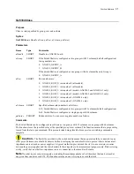
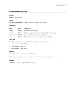
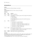
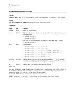
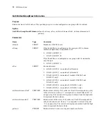
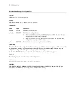
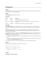
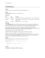
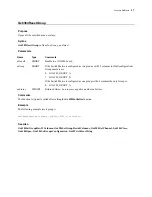
Gx6384Initialize 

Purpose 

Initializes the driver for the board at the specified slot number. The function returns a handle that can be used with 
other GX6384 functions to program the board. 

Syntax 

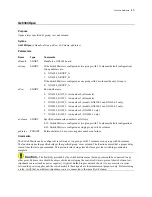
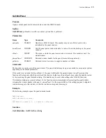
Gx6384Initialize

 (

nSlot, pnHandle, pnStatus

Parameters 

Name 

Type 

Comments 

nSlot 

Short 

GX6384 board slot number on the PXI bus. 

pnHandle 

PSHORT 

Returned handle for the board. The handle is set to zero on error and <> 0 on 
success. 

pnStatus 

PSHORT 

Returned status: 0 on success, negative number on failure. 

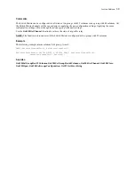
Comments 

The 

Gx6384Initialize

 function verifies whether or not the GX6384 board exists in the specified PXI slot. The 

function does not change any of the board settings. The function uses the HW driver to access and program the 
board.  

The Marvin Test Solutions HW device driver is installed with the driver and is the default device driver. The 
function returns a handle that for use with other Counter functions to program the board. The function does not 
change any of the board settings. 

The specified PXI slot number is displayed by the 

PXI/PCI Explorer

 applet that can be opened from the Windows 

Control Panel

. You may also use the label on the chassis below the PXI slot where the board is installed. The 

function accepts two types of slot numbers: 


A combination of chassis number (chassis # x 256) with the chassis slot number. For example, 0x105 (chassis 1 
slot 5). 


Legacy nSlot as used by earlier versions of HW/VISA. The slot number contains no chassis number and can be 
changed using the 

PXI/PCI Explorer

 applet (1-255).  

The returned handle 

pnHandle

 is used to identify the specified board with other GX6384 functions. 

Example 

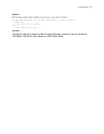
The following example initializes two GX6384 boards at slot 1 and 2. 

 
SHORT nHandle1, nHandle2, nStatus; 
Gx6384Initilize (1, &nHandle1, &nStatus); 
Gx6384Initilize (2, &nHandle2, &nStatus); 
if (nHandle1==0 || nHandle2==0)  

printf(“Unable to Initialize the board”)


return; 

See Also 

Gx6384Reset

GxSWGetErrorString


Summary of Contents for GX6384-1

Page 1: ...GXSW Switching Instruments GX6384 1 GX6384 2 GX6384 3 Configurable High Density Switch Matrix Board User s Guide Last Updated December 15 2016 ...

Page 2: ......

Page 3: ...d Revisions and new versions may be covered by a software support agreement If you need to return a board please contact Marvin Test Solutions Customer Technical Services Department via https www MarvinTest com magic the Marvin Test Solutions on line support system If You Need Help Visit our web site at https www MarvinTest com for more information about Marvin Test Solutions products services and...

Page 4: ... name is Geotest Marvin Test Systems Inc C Builder Delphi Embarcadero Technologies Inc LabVIEW LabWindowstm CVI National Instruments Microsoft Developer Studio Microsoft Visual C Microsoft Visual Basic NET and Windows Microsoft Corporation All other trademarks are the property of their respective owners ...

Page 5: ...itch Matrix Dual 2x32 configured as single group of 2x64 6 GX6384 2 switch Matrix Dual 4x32 configured as two groups A and B each with 32 columns 7 GX6384 2 switch Matrix Dual 4x32 configured as single group of 4x64 8 GX6384 3 switch Matrix Dual 6x32 configured as two groups A and B each with 32 columns 9 GX6384 3 switch Matrix Dual 6x32 configured as single group of 6x64 10 Ground and Guard 10 Sp...

Page 6: ... Jumpers 24 Connectors and Accessories 25 J6 Connector Default mode Matrix configured as two groups A and B 26 J6 Connector Single Group mode Matrix configured as single A with 64 columns 27 Chapter 4 Functions Reference 29 Introduction 29 GX6384 Functions 30 Gx6384Close 31 Gx6384GetBoardSummary 33 Gx6384GetChannel 34 Gx6384GetGroupRow32Columns 36 Gx6384GetGroupRow64Columns 38 Gx6384GetGroupsConfi...

Page 7: ...GX6384 User s Guide v Index 55 ...

Page 8: ...vi GX6384 User s Guide ...

Page 9: ...the GX6384 manual and shows warning conventions used in the manual Chapter 2 Overview Provides the GX6384 list of features description of the board architecture specifications and the virtual panel description and operation Chapter 3 Installation and Connections Provides instructions about how to install a GX6384 board and the GXSW software Chapter 4 Functions Reference Provides a list of the GXSW...

Page 10: ...ield syntax and programming samples Bold type Words or characters you type as the manual instructs For example function or panel names Italic type Specialized terms Titles of other references and information sources Placeholders for items you must supply such as function parameters ...

Page 11: ...bles unprecedented flexibility for different testing requirements The PXI GX6384 is ideal for high channel count automated test configurations Featuring compact reed relays with high switching speeds provides maximum throughput in a test system for signals up to 170 VDC 170 VAC or 0 5 A combined with user friendly 78 pin sub D type interface connector Features The GX6384 is a single slot 3U PXI hi...

Page 12: ...configurations can be programmatically changed to a single group with same number of rows but double the number of columns as single group of 2x64 GX6384 1 single group of 4x64 GX6384 2 or single group of 6x64 GX6384 3 That capability enables unprecedented flexibility for different testing requirements The PXI GX6384 is ideal for high channel count automated test configurations Featuring compact r...

Page 13: ...ps of 2x32 GX6384 1 two groups of 4x32 GX6384 2 or two groups of 6x32 GX6384 3 All three board configurations can be programmatically changed to a single group with same number of rows but double the number of columns as single group of 2x64 GX6384 1 single group of 4x64 GX6384 2 or single group of 6x64 GX6384 3 That capability enables unprecedented flexibility for different testing requirements F...

Page 14: ...13 12 11 10 9 8 7 6 5 4 3 2 1 0 Group A Columns 0 through 31 31 Row A0 Row A1 30 29 28 27 26 25 24 23 22 21 20 19 18 17 16 15 14 13 12 11 10 9 8 7 6 5 4 3 2 1 0 Figure 2 3 GX6384 1 A and B Switching Groups GX6384 1 switch Matrix Dual 2x32 configured as single group of 2x64 Figure 2 4 demonstrates the GX6384 1 model when configured programmatically to as a single group A with 64 columns 3130 29 28 ...

Page 15: ...t configuration settings Group A Columns 0 through 31 31 Row A0 Row A1 30 29 28 27 26 25 24 23 22 21 20 19 18 17 16 15 14 13 12 11 10 9 8 7 6 5 4 3 2 1 0 Row A2 Row A3 Group B Columns 0 through 31 31 Row B0 Row B1 30 29 28 27 26 25 24 23 22 21 20 19 18 17 16 15 14 13 12 11 10 9 8 7 6 5 4 3 2 1 0 Row B2 Row B3 Figure 2 5 GX6384 2 A and B Switching Groups ...

Page 16: ...rogrammatically to as a single group A with 64 columns Row A0 Row A1 Row A2 3130 29 28 27 26 2524 2322 21 20 19 18 17 16 15 14 13 12 11 10 9 8 7 6 5 4 3 2 1 0 63 62 61 60 59 58 57 56 55 54 53 52 51 50 49 48 47 46 45 44 43 424140 39 38 37 36 35 34 33 32 Row A3 Figure 2 6 GX6384 2 Switching Groups A and B configured as a single group A with 64 columns ...

Page 17: ...n settings Group A Columns 0 through 31 Row A0 Row A1 Row A2 Row A3 31 30 29 28 27 26 25 24 23 22 21 20 19 18 17 16 15 14 13 12 11 10 9 8 7 6 5 4 3 2 1 0 Row A4 Row A5 Group B Columns 0 through 31 Row B0 Row B1 Row B2 Row B3 31 30 29 28 27 26 25 24 23 22 21 20 19 18 17 16 15 14 13 12 11 10 9 8 7 6 5 4 3 2 1 0 Row B4 Row B5 Figure 2 7 GX6384 3 A and B Switching Groups ...

Page 18: ...0 29 28 27 26 25 24 2322 21 20 19 18 17 16 15 14 13 12 11 10 9 8 7 6 5 4 3 2 1 0 63 62 61 60 59 58 57 56 55 54 53 52 51 50 49 48 47 46 45 44 43 42 41 40 39 38 37 36 35 34 33 32 Row A3 Row A4 Row A5 Figure 2 8 GX6384 3 Switching Groups A and B configured as a single group A with 64 columns Ground and Guard All the shielding on the GX6384 board is connected to a chassis signal JP1 can be installed t...

Page 19: ...Contact Life 1 x10e9 cycles Rating At 5 VDC 10mA Maximum Switchable Voltage 170 VDC or 170 peak VAC Maximum Switchable Current 500 mA Contact Carry Current 1 Maximum Operate Time 100uS including bounce Release Time 20 S Max number of relays closed at any given time 128 Physical Relay type Reed Relay contact material Rhodium Size 3U PXI Weight 10 6 oz Power Requirements 3 3V Power 0 5A Max 5V Power...

Page 20: ...o initialize the board driver The current settings of the selected board will not change after calling initialize The panel will reflect the current settings of the board after the Initialize dialog closes Reset Resets the PXI board settings to their default state and clears the reading Apply Applies changed settings to the board Close Closes the panel Closing the panel does not affect the board s...

Page 21: ...ocated in the Windows folder These configuration files are also used by VISA The following figure shows the slot number 0x10C chassis 1 Slot 12 This is the slot number argument nSlot passed by the panel when calling the driver Gx6384Initialize function which is used to initialize the driver for the specified board Figure 2 10 Initialize Dialog Box using Marvin Test Solutions HW driver 2 Use VISA T...

Page 22: ...s each The following controls are shown Matrix Configuration radio button Set Displays the current Matrix relays configuration Configuration options are Two Groups Two individual groups A and B with 32 columns each see Figure 2 12 Single Group Single group group A with 64 columns see Figure 2 13 Matrix Group A and B Display Area Displays the current relay setting closed or open When a box in the m...

Page 23: ...Overview 15 Figure 2 13 GX6384 Virtual Panel Initialized with Switch Matrix configured as Single Group with 64 columns ...

Page 24: ... Marvin Test Solutions support The upgrade requires a firmware file jam that is written to the board FPGA After the upgrade is complete you must shut down the computer to recycle power to the board Switch Time Compatibility Mode checkbox When checked switching time will be the same as it was in previous GxSw driver versions regardless of the board s firmware or revision If unchecked default switch...

Page 25: ...ard from the shipping carton Caution Static sensitive devices are present Ground yourself to discharge static 1 Remove the board from the static bag by handling only the metal portions 2 Be sure to check the contents of the shipping carton to verify that all of the items found in it match the packing list 3 Inspect the board for possible damage If there is any sign of damage return the board immed...

Page 26: ...iles x86 Marvin Test Solutions GXSW 5 Select the type of Setup you wish and click Next You can choose between Typical Run Time and Custom setups types The Typical setup type installs all files Run Time setup type will install only the files required for controlling the board either from its driver or from its virtual panel The Custom setup type lets you select from the available components The pro...

Page 27: ...and users to write and use instruments drivers VISA is a standard maintained by the VXI Plug Play System Alliance and the PXI Systems Alliance organizations http www ivifoundation org http www pxisa org The VISA resource manager such as National Instruments Measurement Automation NI MAX displays and configures instruments and their address similar to Marvin Test Solutions PXI PCI Explorer The GXSW...

Page 28: ...ds to identify your system Chassis and Controller manufacturers should provide INI and driver files for their chassis and controllers which are used by these commands 3 Change chassis numbers PXI devices Legacy Slot numbering and PXI devices Alias names These are optional steps and can be performed if you would like your chassis to have different numbers Legacy slots numbers are used by older Marv...

Page 29: ...ctricity Save the anti static bag in case the board is removed from the computer in the future Carefully unpack and install the board Do not drop or handle the board roughly Handle the board by the edges Avoid contact with any components on the circuit board Caution Do not insert or remove any board while the computer is on Turn off the power from the PXI chassis before installation Installing a B...

Page 30: ... shown in Figure 3 3 to secure the module into the frame Error Objects cannot be created from editing field codes Figure 3 3 Ejector handles position after module insertion 7 Tighten the module s front panel to the chassis to secure the module in 8 Connect any necessary cables to the board 9 Plug the power cord in and turn on the PXI chassis ...

Page 31: ...olutions HW On 64 bit systems the HW INF file is located in C Program File x86 Marvin Test Solutions HW If you are unable to locate the driver click Cancel to the found New Hardware wizard and exit the New Hardware Found Wizard install the GXSW driver reboot your computer and repeat this procedure The Windows Device Manager open from the System applet from the Windows Control Panel must display th...

Page 32: ...gure 3 4 shows the GX6384 board connectors and jumpers followed by their description Figure 3 4 GX6384 Connectors and Jumpers J6 Front Connector J6 78 Pin D Type front connector JP1 Guard Ground Used to connect the relay ground layer to ground J6 JP1 ...

Page 33: ...nector D Type 78 pin male with solder pins GT96078 78 pin connector to screw terminal interface GT96107 3 harness 78 pin male connector on both ends GT97102 3 harness 78 pin male connector on one end loose wires numbered other end GT97103 1 harness 78 pin male connector on one end loose wires numbered other end GT97104 1 harness 78 pin male connectors on both ends Figure 3 5 GX6384 front Connector...

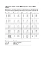
Page 34: ... Col B4 64 Col B20 6 Col A5 26 Col A21 45 Col B5 65 Col B21 7 Col A6 27 Col A22 46 Col B6 66 Col B22 8 Col A7 28 Col A23 47 Col B7 67 Col B23 9 Col A8 29 Col A24 48 Col B8 68 Col B24 10 Col A9 30 Col A25 49 Col B9 69 Col B25 11 Col A10 31 Col A26 50 Col B10 70 Col B26 12 Col A11 32 Col A27 51 Col B11 71 Col B27 13 Col A12 33 Col A28 52 Col B12 72 Col B28 14 Col A13 34 Col A29 53 Col B13 73 Col B29...

Page 35: ...25 Col A20 44 Col A36 64 Col A52 6 Col A5 26 Col A21 45 Col A37 65 Col A53 7 Col A6 27 Col A22 46 Col A38 66 Col A54 8 Col A7 28 Col A23 47 Col A39 67 Col A55 9 Col A8 29 Col A24 48 Col A40 68 Col A56 10 Col A9 30 Col A25 49 Col A41 69 Col A57 11 Col A10 31 Col A26 50 Col A42 70 Col A58 12 Col A11 32 Col A27 51 Col A43 71 Col A59 13 Col A12 33 Col A28 52 Col A44 72 Col A60 14 Col A13 34 Col A29 53...

Page 36: ...28 GX6384 User s Guide ...

Page 37: ... programming and controlling the operation of that board All functions return a status with the last parameter named pnStatus The pnStatus is zero if the function was successful or less than a zero on error The description of the error is available using the GxSWGetErrorString function or by using a predefined constant defined in the driver interface files GXSW H GXSW BAS GXSW PAS or GX6384 DRV Pa...

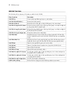
Page 38: ...ified slot number The function returns a handle that can be used with other GX6384 functions to program the board Gx6384InitializeVisa Initializes the driver for the specified slot using VISA The function returns a handle that can be used with other GX6384 functions to program the board Gx6384Open Opens a relay specified by group row and column Gx6384Panel Opens a virtual panel used to interactive...

Page 39: ...roup with 64 columns pnStatus PSHORT Returned status 0 on success negative number on failure Comments The Switch Matrix can be configured via software as two groups with 32 columns or one group with 64 columns The function closes the specified relay at the specified group s row column The function ensures that a proper delay is used from the last open command This prevents relay being closed befor...

Page 40: ...ple closes relay at group A row 1 relay 0 Gx6384Close nHandle GX6384_GROUP_A GX6384_ROW_1 0 nStatus See Also Gx6384SetGroupRow32Columns Gx6384SetGroupRow64Columns Gx6384GetChannel Gx6384Close Gx6384Open Gx6384SetGroupsConfiguration GxSWGetErrorString ...

Page 41: ... contain the board info string pnStatus PSHORT Returned status 0 on success negative number on failure Comments The GX6384 summary string provides the following data from in the order shown Instrument Name e g GX6384 FPGA version e g 0xA002 Serial Number e g 63840210 Example For example the returned string looks like the following GX6384 2 Switch Matrix Dual 4x32 FPGA Version 0xA003 S N 63841234 E...

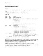
Page 42: ..._3 row number 3 models GX6384 2 and GX6384 3 only 4 GX6384_ROW_4 row number 4 GX6384 3 only 5 GX6384_ROW_5 row number 5 GX6384 3 only nColumn SHORT Specified column relay number is as follows 0 31 Switch Matrix is configured as two groups with 32 columns default configuration 0 63 Switch Matrix is configured as single group with 64 columns pnState PSHORT Returned state of the relay 1 for close and...

Page 43: ...is closed Gx6384GetChannel nHandle GX6384_GROUP_A GX6384_ROW_0 3 nState nStatus if nClose 1 printf A0 3 relay is closed else printf A0 3 relay is open See Also Gx6384SetGroupRow32Columns Gx6384SetGroupRow64Columns Gx6384GetChannel Gx6384Close Gx6384Open Gx6384SetGroupsConfiguration GxSWGetErrorString ...

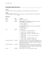
Page 44: ...ROW_3 row number 3 models GX6384 2 and GX6384 3 only 4 GX6384_ROW_4 row number 4 GX6384 3 only 5 GX6384_ROW_5 row number 5 GX6384 3 only pdwStates PDWORD Returned state of the relays in the row Each bit corresponds to a relay in the selected row where a 1 corresponds to a closed relay and 0 to an open relay The low order bit represents column 0 and the high order bit represents column 31 pnStatus ...

Page 45: ...mns 0 31 of group A row 0 DWORD dwStates Gx6384GetGroupRow32Columns nHandle GX6384_GROUP_A GX6384_ROW_0 dwStates nStatus See Also Gx6384SetGroupRow32Columns Gx6384SetGroupRow64Columns Gx6384GetChannel Gx6384Close Gx6384Open Gx6384SetGroupsConfiguration GxSWGetErrorString ...

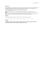
Page 46: ...6384_ROW_1 row number 1 all models 2 GX6384_ROW_2 row number 2 models GX6384 2 and GX6384 3 only 3 GX6384_ROW_3 row number 3 models GX6384 2 and GX6384 3 only 4 GX6384_ROW_4 row number 4 GX6384 3 only 5 GX6384_ROW_5 row number 5 GX6384 3 only dwStatesColumns32to63 PDWORD Returned state of relays 0 31 in the row Each bit corresponds to a relay in the selected row where a 1 corresponds to a closed r...

Page 47: ...the Gx6384GetChannel function to retrieve the state of a specific relay NOTE The function returns an error if the Switch Matrix is configured as two groups with 32 columns Example The following example returns columns 0 63 group A row 0 DWORD dwStatesColumns32to63 dwStatesColumns0to31 Gx6384GetRow nHandle GX6384_GROUP_A GX6384_ROW_0 dwStatesColumns32to63 dwStatesColumns0to31 nStatus See Also Gx638...

Page 48: ...ess negative number on failure Comments The Switch Matrix can be configured via software as two groups with 32 columns or one group with 64 columns All the Switch Matrix channels will be opened prior to applying the new configuration settings Applying the same configuration settings will not change the current group s channels settings Use the Gx6384GetRow function to retrieve the state of all rel...

Page 49: ...function returns a handle that for use with other Counter functions to program the board The function does not change any of the board settings The specified PXI slot number is displayed by the PXI PCI Explorer applet that can be opened from the Windows Control Panel You may also use the label on the chassis below the PXI slot where the board is installed The function accepts two types of slot num...

Page 50: ...nt szVisaResource is a string that is displayed by the VISA resource manager such as NI Measurement and Automation NI_MAX It is also displayed by Marvin Test Solutions PXI PCI Explorer as shown in the prior figure The VISA resource string can be specified in several ways as follows Using chassis slot for example PXI0 CHASSIS1 SLOT5 Using the PCI Bus Device combination for example PXI9 13 INSTR bus...

Page 51: ...ured as two groups with 32 columns default configuration 0 63 Switch Matrix is configured as single group with 64 columns pnStatus PSHORT Returned status 0 on success negative number on failure Comments The Switch Matrix can be configured via software as two groups with 32 columns or one group with 64 columns The function opens the specified relay at the specified group s row column The function e...

Page 52: ...mple opens relay at group A row 1 relay 0 Gx6384Open nHandle GX6384_GROUP_A GX6384_ROW_1 0 nStatus See Also Gx6384SetGroupRow32Columns Gx6384SetGroupRow64Columns Gx6384GetChannel Gx6384Close Gx6384Open Gx6384SetGroupsConfiguration GxSWGetErrorString ...

Page 53: ...create the panel window The panel window may be open as a modal or a modeless window depending on the nMode parameters If the mode is set to modal dialog nMode 1 the panel will disable the parent window hwndParent and the function will return only after the user closed the window In that case the pnHandle may return the handle created by the user using the panel Initialize dialog This handle may b...

Page 54: ...atus PSHORT Returned status 0 on success negative number on failure Comments The function is typically called after calling the Gx6384Initialize function Example The following example initializes the driver and then resets the board Gx6384Initilize 1 nHandle nStatus if nStatus 0 return nStatus return error Gx6384Reset nHandle nStatus See Also Gx6384Initialize GxSWGetErrorString ...

Page 55: ...384_GROUP_A 1 GX6384_GROUP_B If the Switch Matrix is configured as one group with 64 columns the only Group is 0 GX6384_GROUP_A pnStatus PSHORT Returned status 0 on success negative number on failure Comments The function is typically called after calling the Gx6384Initialize function Example The following example resets group A Gx6384ResetGroup nHandle GX6384_GROUP_A nStatus See Also Gx6384SetGro...

Page 56: ...5 row number 5 GX6384 3 only dwStates DWORD Sets the state of the relays 0 31 in the row Each bit corresponds to a relay in the selected row where a 1 corresponds to a closed relay and 0 to an open relay The low order bit represents column 0 and the high order bit represents the last column pnStatus PSHORT Returned status 0 on success negative number on failure Comments The Switch Matrix can be co...

Page 57: ...ys 0 1 4 8 and 19 in group A row 0 Gx6384SetGroupRow32Columns nHandle GX6384_GROUP_A GX6384_ROW_0 0x80113 nStatus See Also Gx6384SetGroupRow32Columns Gx6384SetGroupRow64Columns Gx6384GetChannel Gx6384Close Gx6384Open Gx6384SetGroupsConfiguration GxSWGetErrorString ...

Page 58: ... GX6384_ROW_1 row number 1 all models 2 GX6384_ROW_2 row number 2 models GX6384 2 and GX6384 3 only 3 GX6384_ROW_3 row number 3 models GX6384 2 and GX6384 3 only 4 GX6384_ROW_4 row number 4 GX6384 3 only 5 GX6384_ROW_5 row number 5 GX6384 3 only dwStatesColumns32to63 DWORD Returned state of relays 0 31 in the row Each bit corresponds to a relay in the selected row where a 1 corresponds to a closed...

Page 59: ...The function returns an error if the Switch Matrix is configured as two groups with 32 columns Note In order to prevent power supply overloading the maximum number of all the relays that can be closed at any given time cannot exceed 128 The function returns an error if trying to exceed the limit Example The following example close relays 0 1 4 8 and 19 34 36 40 44 63 in group A row 0 Gx6384SetGrou...

Page 60: ...negative number on failure Comments The Switch Matrix can be configured via software as two groups with 32 columns or one group with 64 columns Note All the Switch Matrix channels will be opened prior to applying the new configuration settings Applying the same configuration settings will not change the current group s channels settings Use the Gx6384GetRow function to retrieve the state of all re...

Page 61: ...re Comments The function returns the error string associated with the nError as returned from other driver functions This function returns error value or 0 on success The following table displays the possible error values not all errors apply to this board type Resource Errors 1 Board does not exist in this slot 2 Unable to open the HW device Service 3 Different board exist in the specified PCI sl...

Page 62: ...ber is out of range 62 Error specified number of relays is out of range 63 Error specified relays cycles limit is out of range 64 Error specified relay cycles array size is out of range 65 Error EPROM communication generated timeout 66 Error Trying to close more relays then allowed by this board type at any given time Miscellaneous Errors 99 Invalid or unknown error number Example The following ex...

Page 63: ...Gx6384GetChannel 34 Gx6384GetGroupRow32Columns 36 Gx6384GetGroupRow64Columns 38 Gx6384GetGroupsConfiguration 40 Gx6384Initialize 13 29 41 Gx6384InitializeVisa 13 20 30 42 Gx6384Open 43 Gx6384Panel 45 Gx6384Reset 46 Gx6384ResetGroup 47 Gx6384SetGroupRow32Columns 48 Gx6384SetGroupRow64Columns 50 Gx6384SetGroupsConfiguration 52 GXSW 18 GXSW EXE 18 GxSWGetErrorString 29 53 H Handle 21 22 HW 18 19 23 I...

Page 64: ...rogrammed to one group of 2x64 6 Configuration programmed to one group of 4x64 8 Configuration programmed to one group of 6x6410 Switch Matrix 6 switch Matrix Dual 4x32 7 switch Matrix Dual 6x32 9 Switch Matrix Groups 6 System Directory 19 T Trademarks 2 V Virtual Panel Setup Page 14 Virtual Panel 12 13 14 Initialize Dialog 13 Virtual Panel 16 Virtual Panel About Page 16 Virtual Panel 18 Virtual P...

Reviews: