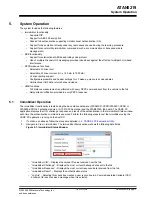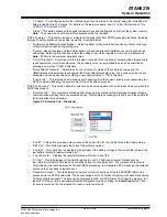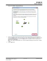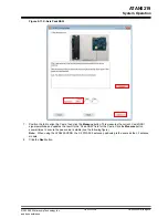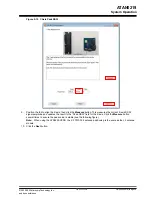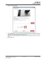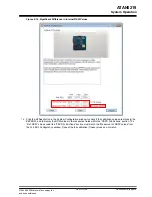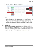
• “LF Challenge” – Displays the 4-byte LF challenge data that was sent to the fob. This challenge data is sent
during bilateral and unilateral authentication.
• “LF Encrypted Challenge” – Displays the 4-byte LF encrypted data sent to the fob during bilateral authentication
only.
• “RF MAC” – Displays the received RF MAC value from the fob.
• “Localization” – Displays the current localization status of the current fob (for example, inside or outside the
vehicle). This is determined by comparing the distance scale value against the “In/Out Threshold (RSSI)” value
displayed in the System Configuration window (see
Note:
The fob section is highlighted in blue if the fob is found “inside” and pink if the fob is found “outside.” This
allows for an easy determination from a distance while the range of the system is being tested.
• “Distance Scale” – Indicates the RSSI scale value received.
• “Coil Phase Signature” – Displays a three-digit binary code (see the following table):
•
Table 5-2. Coil Phase Signature Calculation
Bit
Position
Calculation Using Coil Phase Clock
Count Values
Bit Value (If 90° < Calculated Result
< 270°)
Bit Value
(Otherwise)
1
Z − Y value
360 value x 360
1
0
2
Z − X value
360 value x 360
1
0
3
Y − X value
360 value x 360
1
0
Note:
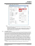
The Z-Y, Z-X, Y-X and 360 coil phase clock count values are found in the “PEPS Fob Actions” section of
the System Configuration window.
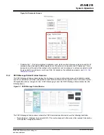
• “TOF Measured (cm)” – Displays the Time of Flight measured between the vehicle and the fob.
Notes:
• The Relay Attack icon appears when both ATA8352-XPRO boards are connected and the “TOF Measured
(cm)” value is greater than the “Relay Attack Threshold (cm)” value or if the fob does not return a measured
value.
• The Battery Low icon appears if the fob returns a low voltage warning indicating the battery voltage is
below 2.6V (approximately).
• “Log PEPS transaction to file ” – Selecting this check box creates a new record line in a CSV document for each
received message when it is selected.
• “PEPS Commands” – This section includes controls for initiating various PEPS functions and their associated
authentication used.
– “Start/Stop” – This button initiates either the start or stop PEPS function depending on the status of the
vehicle.
– “Unlock” – This button initiates the unlock PEPS function.
– “Lock” – This button initiates the lock PEPS function.
– “Unilateral and Bilateral Authentication” – Selecting either of these radio buttons has an effect on the type
of communication used during the selected PEPS commands.
5.3.3
Identifying FOBS within LF Range
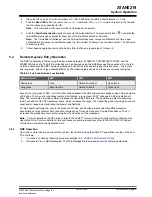
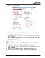
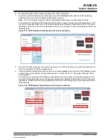
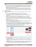
Identify the available fobs by sending out a broadcast, which returns the Fob# in the selected fob field. Perform the
following steps to identify the available fobs within the LF range:
1.
If not done already, follow the procedure detailed in
4. CARS Kit PC Evaluation Utility
.
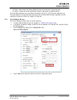
2.
In the System Configuration window, choose
Broadcast
from the “Selected Fob” drop-down list (see
3.
Click the
Fob ID
button to send the broadcast request. The available fobs respond with their fob IDs and their
Fob# assignments. The “Fob Vehicle ID” field displays the returned vehicle ID.
4.
Click the
S/W Ver
button to send the software version request to the fob. The “S/W Ver” field displays the
returned software version number.
ATAN0219
System Operation
©
2020-2022 Microchip Technology Inc.
and its subsidiaries
User Guide
DS50003051B-page 20

