3 . 6
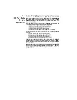
Registers R16 and R17 function as intermediate data storage regis-
I/O Port Data
ters between the PSG/CPU data bus (DA0--DA7) and the two I/O
ports (IOA7-IOA0 and
IOB7--1OB0).
Both ports are available in the
Store
AY-3-8910; only
I/O
Port A is available in the AY-3-8912. Using
registers R16 and R17 for the transfer of
I/O
data has no effect at all
(Registers R16, R17)
on sound generation.
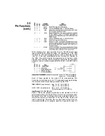
To output data from the CPU bus to a peripheral device connected
to I/O Port A would require only the following steps:
1. Latch address R7 (select Enable register)
2. Write data to PSG (setting B6 of R7 to “1”)
3. Latch address R16 (select IOA register)
4. Write data to PSG (data to be output on
I/O
Port A)
To input data from I/O Port A to the CPU bus would require the
following:
1. Latch address R7 (select Enable register)
2. Write data to PSG (setting B6 to R7 to “0”)
3. Latch address R16 (select IOA register)
4. Read data from PSG (data from I/O Port A)
Note that once loaded with data in the output mode, the data will
remain on the I/O port(s) until changed either by loading different
data, by applying a reset (grounding the Reset pin), or by switching to
the input mode.
Note also that when in the input mode, the contents of registers R16
and/or R17 will follow thesignals applied to the I/O port(s). However,
transfer of this data to the CPU bus requires a “read” operation as
described above.
Summary of Contents for ay-3-8910
Page 2: ...AY 3 8910 8912 PROGRAMMABLE SOUND GENERATOR DATA MANUAL...
Page 7: ......
Page 8: ......
Page 10: ......
Page 26: ......
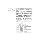
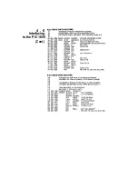
Page 35: ...4 6 Interfacing to the PIC 1650 Cont...
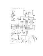
Page 36: ...Fig 19 PIC 1650 AY 3 6910 SYSTEM EXAMPLE...
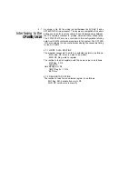
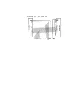
Page 38: ...Fig 20 CP1600 1610 AY 3 8910 INTERFACE...
Page 40: ...Fig 21 M6800 AY 3 8910 INTERFACE...
Page 42: ......
Page 44: ......
Page 52: ...7 ELECTRICAL SPECIFICATIONS...
Page 54: ...7 ELECTRICAL SPECIFICATIONS...
Page 55: ......
Page 56: ......

