USB5744
DS00001855E-page 20
2015-2017 Microchip Technology Inc.
5.1
Boot Sequence
5.1.1
STANDBY MODE
If the
RESET_N
pin is asserted, the hub will be in Standby Mode. This mode provides a very low power state for maxi-
mum power efficiency when no signaling is required. This is the lowest power state. In Standby Mode all downstream
ports are disabled, the USB data pins are held in a high-impedance state, all transactions immediately terminate (no
states saved), all internal registers return to their default state, the PLL is halted, and core logic is powered down in order
to minimize power consumption. Because core logic is powered off, no configuration settings are retained in this mode
and must be re-initialized after
RESET_N
is negated high.
5.1.2
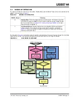
SPI INITIALIZATION STAGE (SPI_INIT)
The first stage, the initialization stage, occurs on the deassertion of
RESET_N
. In this stage, the internal logic is reset,
the PLL locks if a valid clock is supplied, and the configuration registers are initialized to their default state. The internal
firmware then checks for an external SPI ROM. The firmware looks for an external SPI flash device that contains a valid
signature of “2DFU” (device firmware upgrade) beginning at address 0xFFFA. If a valid signature is found, then the
external ROM is enabled and the code execution begins at address 0x0000 in the external SPI device. If a valid signa-
ture is not found, then execution continues from internal ROM (CFG_RD stage).
When using an external SPI ROM, a 1 Mbit, 60 MHz or faster ROM must be used. Both 1- and 2-bit SPI operation are
supported. For optimum throughput, a 2-bit SPI ROM is recommended. Both mode 0 and mode 3 SPI ROMs are also
supported.
If the system is not strapped for SPI Mode, code execution will continue from internal ROM (CFG_RD stage).
5.1.3
CONFIGURATION READ STAGE (CFG_RD)
In this stage, the internal firmware loads the default values from the internal ROM and then uses the configuration strap-
ping options to override the default values. Refer to
Section 3.4, "Configuration Straps and Programmable Functions"
for information on usage of the various device configuration straps.
5.1.4
STRAP READ STAGE (STRAP)
In this stage, the firmware registers the configuration strap settings on the
SPI_DO
and
SPI_CLK
pins. Refer to
3.4.1, "SPI/SMBus Configuration"
for information on configuring these straps. If configured for SMBus Slave Mode, the
next state will be SOC_CFG. Otherwise, the next state is OTP_CFG.
5.1.5
SOC CONFIGURATION STAGE (SOC_CFG)
In this stage, the SOC can modify any of the default configuration settings specified in the integrated ROM, such as USB
device descriptors and port electrical settings.
There is no time limit on this mode. In this stage the firmware will wait indefinitely for the SMBus/I
2
C configuration. When
the SOC has completed configuring the device, it must write to register 0xFF to end the configuration.
5.1.6
OTP CONFIGURATION STAGE (OTP_CFG)
Once the SOC has indicated that it is done with configuration, all configuration data is combined in this stage. The
default data, the SOC configuration data, and the OTP data are all combined in the firmware and the device is pro-
grammed.
After the device is fully configured, it will go idle and then into suspend if there is no VBUS or Hub.Connect present.
Once VBUS is present, and battery charging is enabled, the device will transition to the Battery Charger Detection
Stage. If VBUS is present, and battery charging is not enabled, the device will transition to the Connect stage.
5.1.7
HUB CONNECT STAGE (HUB.CONNECT)
Once the CHGDET stage is completed, the device enters the Hub Connect stage. USB connect can be initiated by
asserting the VBUS pin function high. The device will remain in the Hub Connect stage indefinitely until the VBUS pin
function is deasserted.


