OPERATING INSTRUCTIONS
4-12
M68HC11EVB/D
BR
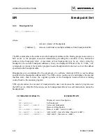
Breakpoint Set
4.6.3
Breakpoint Set
BR [-][<address>]...
where:
-
removes (clears) all breakpoints.
- [<address>]...
removes individual or multiple addresses from breakpoint table.
The BR command sets the address into the breakpoint address table. During program execution, a
halt occurs to the program execution immediately preceding the execution of any instruction
address in the breakpoint table. A maximum of four breakpoints may be set. After setting the
breakpoint, the current breakpoint addresses, if any, are displayed. Whenever the G, CALL, or P
commands are invoked, the monitor program inserts breakpoints into the user code at the address
specified in the breakpoint table.
Breakpoints are accomplished by the placement of a software interrupt (SWI) at each address
specified in the breakpoint address table. The SWI service routine saves and displays the internal
machine state, then restores the original opcodes at the breakpoint location before returning
control back to the monitor program.
SWI opcode cannot be executed or breakpointed in user code because the monitor program uses
the SWI vector. Only RAM locations can be breakpointed. Branch on self instructions cannot be
breakpointed.
COMMAND FORMATS
DESCRIPTION
BR
Display all current breakpoints.
BR <address>
Set breakpoint.
BR <addr1> <addr2> ...
Set several breakpoints.
BR -
Remove all breakpoints.
BR -<addr1> <addr2>...
Remove <addr1> and add <addr2>.
BR <addr1> - <addr2>...
Add <addr1>, clear all entries, then add <addr2>.
BR <addr1> -<addr2>...
Add <addr1>, then remove <addr2>.
Summary of Contents for M68HC11EVB
Page 9: ...CONTENTS x M68HC11EVB D ...
Page 35: ...MONITOR PROGRAM 3 8 M68HC11EVB D ...
Page 81: ...OPERATING INSTRUCTIONS 4 46 M68HC11EVB D ...
Page 97: ...SUPPORT INFORMATION 6 12 M68HC11EVB D Figure 6 3 EVB Schematic Diagram Sheet 2 of 2 ...
Page 103: ...APPLICATIONS B 2 M68HC11EVB D Figure B 1 Single Chip Mode Configuration ...

