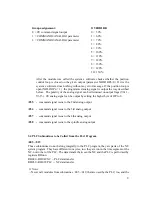
8
3.3 Subroutines Provided by the Manufacturer (to be called from the PLC)
It is a continuously expanded library of subroutines.
:050
-
:059
Those modules may not be used optionally. None of the modules of the above numbers may
be included in the PLC program, only reference may be made to them with instruction C05n.
Whenever the compiler finds such a module, it will return an error signal.
:052
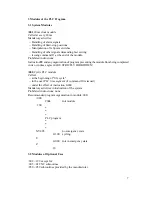
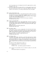
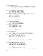
- Issuing a main drive analog signal from the OP. The D/A converter of the main drive
has a resolution of 14 bits. Accordingly, the output analog signal is +10V or -10V
when 4096 or -4096 is loaded in the D/A, respectively.
U
ki
OP
DRIFT6
4096
10V
The content of the OP is not written directly into the D/A, but the value set for
parameter DRIFT6 (PAR4126) is added to it.
:053
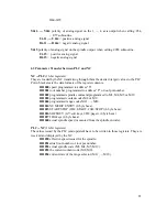
- Computation and outputting of the analog signal in register RH050, pertaining to the
desired speed. The subroutine checks to see that the desired speed can be output in
the particular range. If the desired speed is higher than the maximum speed of the
current range, it will effectuate the maximum speed; if it is lower than the minimum
speed in that range, it will effectuate the minimum one in the range concerned. The
term "desired speed" refers to the programmed one modified by the spindle override.
In the case of an override disable , the subroutine will ignore the override setting, to
adjust 100%. The contents of registers OP and RH050 remain unchanged.
:054
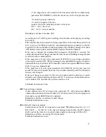
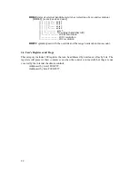
- command signal issue to the 1st analog output
An analog signal proportional to the values on parameters COMMAND1 és
COMMAND2 (parameter No. 0121) can be issued to an arbitrary analog output of
the control. On parameters ANALOG1 and ANALOG2 (parameter No. 0141) limit
values can be determined similar way like for the spindle. The analog signal can be
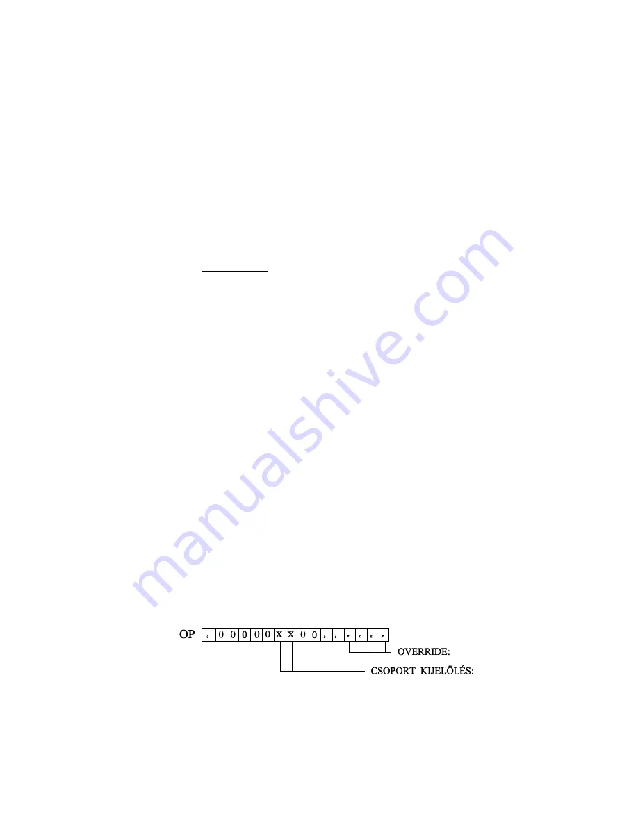
given out by calling this subroutine. On the lower byte of OP the override value can
be set, while on the higher byte the parameter group whose value to be output can be
set.

