21
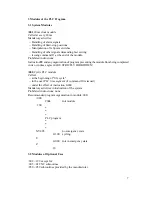
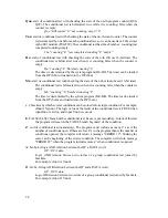
I460-I472.
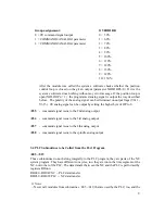
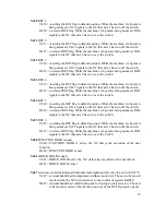
Y611, ..., Y614
polarity of analog signal on the 1, ..., 4. axis output when calling :054,
... :057 subroutine
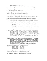
U611, ..., U614
= positive analog signal
D611, ..., D614
= negatív analog signal
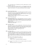
Y615
polarity of analog signal on the spindle output when calling C058 subroutine
U615
= positive analog signal
D615
= negatív analog signal
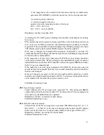
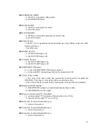
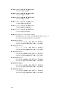
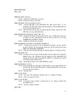
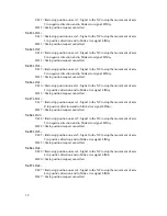
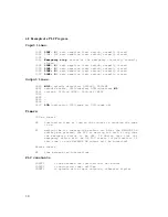
4.3 Parameter Transfer between PLC and NC
NC
$$$$
PLC
(16-bit registers)
They are loaded by the NC transferring through them the desired (target) values to the PLC.
Put in brackets are the data formats of the register contents.
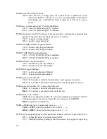
RH000
speed programmed to address "S"
RH001
tool number programmed to address "T" or tool pot number.
RH002
programmed spindle command programmed to M3, M4, M5 or M19.
RH003
programmed coolant codes M8 or M9.
RH004
programmed range codes M11, ..., M18.
RH014
NUMERIC ENTRY (2-byte hexa).
RH015
START/STOP (21H=START, 20H=STOP) (2-byte hexa).
RH016
SOFTKEY (0-7=soft keys, 2FH=pager) (2-byte hexa).
RH017
JOG keys (2-byte hexa).
RH040
actual spindle speed measured from the spindle encoder.
PLC
$$$$
NC
(16-bit registers)
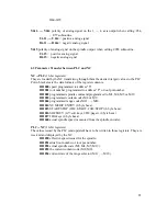
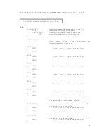
The values issued by the PLC (and updated) have to be written in those registers. They are
received and displayed by the NC.
RH050
effective speed issued for the spindle.
RH051
actual tool number or tool pot number.
RH052
actual spindle code (M3, M4, M5, M19).
RH053
the current coolant code (M8, M9).
RH054
current state of the range selector (M11, ..., M18).

