4
Installation
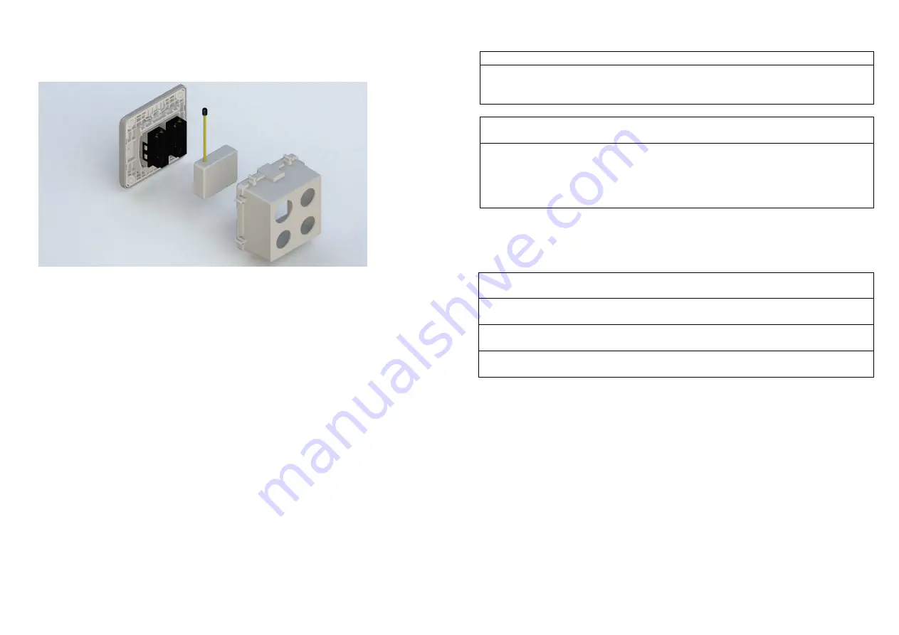
1. Put the in wall switch into a wall box and connect the AC power wire L, N to
PAN35 connector L, N.
2. Connect the wall switch to the PAN35 as Fig1 .
3. There are 3 mode PAN35 can be configured to match different kind of wall
switch, please refer to 3-1
External switch mode
which described in next
section of this user manual
4. If Edge-Toggle mode has been set, and the S1 S2 is connect to normal
bi-stable switch, every time when change the state of the wall switch will also
swap the state of Relay1 or Relay2
Programming
1. Basic Command Class / Binary Switch Command Class
The Switch will respond to BASIC and BINARY commands that are part of the
Z-Wave system.
1-1 BASIC_GET / BINARY_SWITCH_GET
Since the switch have two relay, the Switch will report its On/Off state of relay1
and relay2.
Report ON when either relay 1 ON or relay 2 ON.
Report OFF when both relay 1 and relay 2 OFF.
Basic Get Command: [Command Class Basic, Basic Get]
Basic Report Command:
Report OFF: [Command Class Basic, Basic Report, Value = 0(0x00)]
Report ON:[Command Class Basic, Basic Report, Value = 255(0xFF)]
Binary Switch Get Command:[Command Class Switch Binary, Switch Binary
Get]
Binary Switch Report Command:
Report OFF:[Command Class Switch Binary, Switch Binary Report, Value
=0(0x00)]
Report ON:[Command Class Switch Binary, Switch Binary Report, Value =
255(0xFF)]
1-2 BASIC_SET / SWITCH_BINARY_SET
Since the switch has two relay, both the load attached to the Switch will turn
on or off upon receipt of the following commands from a Z-Wave Controller.
[Command Class Basic, Basic Set, Value = 1~99, 255(0xFF)]: both the load
attached to the Switch turns on.
[Command Class Basic, Basic Set, Value = 0(0x00)]: both the load attached to
the Switch turns off.
[Command
Class
Switch
Binary,
Switch
Binary
Set,
Value
=
1~99,255(0xFF)]: both the load attached to the Switch turns on.
[Command Class Switch Binary, Switch Binary Set, Value = 0(0x00)]: both
the load attached to the Switch turns off.
1. Z-Wave’s Groups (Association Command Class Version 2)
The Switch can be set to send reports to the associated Z-Wave devices. It
supports three groups and every group has five nodes support. Group1 is called
Lifeline which support SWITCH_BINARY_REPORT
、
NOTIFICATION_REPORT
、
INDICATOR_REPORT and DEVICE_RESET_LOCALLY_NOTIFICATION.
Group2 and Group3 are support SWITCH_BINARY_REPORT.
For group 1, the Switch will report ON/OFF status of Relay1 and Relay2
For group 2, the Switch will report ON/OFF status of Relay1
For group 3, the Switch will report ON/OFF status of Relay2
2-1 Auto report to Grouping 1 ~3(Maximum Node 5)
2-1-1 On/Off Event Report


