Operation
34
Magellan Motion Processer Developer’s Kit Manual
2
2.4.3
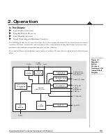
Pulse & Direction Input Over QuadA, QuadB
The Magellan DK card supports an alternate decoding scheme for the QuadA and QuadB position input signals
consisting of pulse & direction position feedback interpretation.
Normally, the QuadA and QuadB signals are interpreted to be quadrature encoded. After passing through the
differential receiver circuitry they are output as digital logic levels directly to the Magellan IC, which only supports
quadrature encoded signals at these two pins.
The Magellan DK includes logic circuitry external to the Magellan IC which, when enabled, converts incoming pulse
& direction signals into corresponding quadrature encoded signals. After conversion, these quadrature-encoded
signals are passed to the Magellan IC where they are used to accumulate the feedback position in the normal manner.
This capability can be set on a per-axis basis, meaning that some axes can be set to input quadrature-encoded signals,
and other axes can input pulse & direction-encoded signals. Selection of standard (no conversion) or converting (pulse
& direction to quadrature conversion) signal processing is controlled via dip switches S5.4, S5.8, S6.4 and S6.8.
The primary use of this feature is to allow position command input from external pulse & direction output motion
controllers. Inputting this position data stream into Magellan is useful for:
• Electronic gear or cam position command input
• Analysis of an external controller’s pulse & direction profile
• Setup and optimization of systems that will use Atlas amplifiers in pulse & direction signal input mode.
The table below shows hot to set the QuadA and QuadB input mode:
2.4.4
Analog Input
The
Analog0-7
signals provide general purpose input of 8 analog signals. If connected, the voltages present at these
various connections do not directly affect the motion processor’s behavior. However they can be read through the
motion processor, and thus provide a convenient way of bringing in analog signal levels that may be acted upon by the
user’s application code located on the PC. These signals are read using the Magellan command
ReadAnalog
. In
conjunction with the
Analog0-7
signals, the user must also provide a number of other signals that provide analog
reference scaling to the Magellan Motion Processor. These signals are summarized in the table below:
Item
Switch
Description
Dip switch S5-4
up
Sets QuadA and QuadB interpretation for Axis 1 to quadrature
down
Sets QuadA and QuadB interpretation for Axis 1 to pulse & direction
Dip switch S5-8
up
Sets QuadA and QuadB interpretation for Axis 2 to quadrature
down
Sets QuadA and QuadB interpretation for Axis 2 to pulse & direction
Dip switch S6-4
up
Sets QuadA and QuadB interpretation for Axis 3 to quadrature
down
Sets QuadA and QuadB interpretation for Axis 3 to pulse & direction
Dip switch S6-8
up
Sets QuadA and QuadB interpretation for Axis 4 to quadrature
down
Sets QuadA and QuadB interpretation for Axis 4 to pulse & direction
Signal name
Function
AnalogRefLow
Provides minimum allowed analog voltage input signal. Has an allowed range of 0 to 3.3V.
Generally connected to 0 volts.
AnalogRefHigh
Provides maximum allowed analog voltage input signal. Has an allowed range of 0 to 3.3V,
but must be greater than
AnalogRefLow
. Generally connected to 3.3 volts.
AnalogGND
Provides ground return for reference and analog input signals


