Operation
Magellan Motion Processer Developer’s Kit Manual
27
2
The system on which the Magellan Developer’s Kit card is installed can control the card through the pre-compiled
program Pro-Motion, or through a program of their own construction, using C-Motion calls as the basic interface.
During axis setup, the communications method (PCI-bus, serial port, or CANbus) and other parameters are specified,
which allow C-Motion to create a virtualized axis handle, that from then on is the reference for all C-Motion
commands.
Available C-Motion commands correspond one-for-one with those listed in the
Magellan Motion Processor Programmer's
Command Reference
. All C-Motion commands preface the Magellan command with the letters “PMD,” so the Magellan
command (for example)
SetPosition
becomes the C-callable routine.
PMDSetPosition
Example
The following simple example, to set up and execute a simple trapezoidal profile, illustrates just a small part of the
overall command set.
PMDSetProfileMode(axis_handle, trapezoidal);
PMDSetPosition(axis_handle, position_value);
PMDSetVelocity(axis_handle, velocity_value);
PMDSetAcceleration(axis_handle, acceleration_value);
PMDSetDeceleration(axis_handle, deceleration_value);
PMDUpdate(axis_handle);
Two separate manuals describe how the Magellan Motion Processor operates and how it is programmed, the
Magellan
Motion Processor User’s Guide
and the
Magellan Motion Processor Programmer's Command Reference.
2.3
Card Specific Functions
Card-specific functions are those functions that are mapped through the motion processor’s ReadIO and WriteIO
facility, but are implemented in the card circuitry.
Card-specific functions are detailed in this document rather than the
Magellan Motion Processor User’s Guide
or the
Magellan Motion Processor Programmer’s Command Reference.
2.3.1
General Purpose Digital IO
In addition to numerous special-purpose digital signals that are input or output to the card such as
AxisIn, AxisOut, Home,
QuadA
,
etc., the Magellan Developer’s Kit cards support 8 general-purpose inputs, and 8 general-purpose outputs.
These signals provide a convenient way of accessing additional general purpose digital IO. Although access to these
signals occurs through the motion processor’s
ReadIO
and
WriteIO
command, the signals present at these various
connections do not directly affect the motion processor’s behavior. Thus the motion processor simply passes them
through.
ReadIO and WriteIO Commands
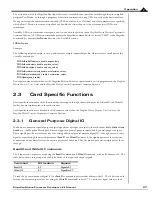
The 8 inputs and outputs are read using the
ReadIO
command and
WriteIO
command, with an IO address of 0. The
table below shows this, along with the bit locations of the input and output signals.
To read the 8 general purpose digital I/Os, a
ReadIO
command is performed at address offset 0. The 16 bit read word
returns the current output values (set using the
WriteIO
command) in bits 0-7. To write new signal values to the 8
Command
Bit location
Signals
ReadIO 0
0-7
DigitalIn0-7
WriteIO 0
0-7
DigitalOut0-7

