Operation
Magellan Motion Processer Developer’s Kit Manual
35
2
All of the analog signals described in this section are directly connected to the corresponding pins on the Magellan
Motion Processor. For more information on reading the value of these analog inputs, see the
Magellan Motion Processor
User’s Guide.
Connections & Associated Signals
For analog voltages to be read correctly, in addition to the analog signals
Analog0-7
themselves,
AnalogRefLow
,
AnalogRefHigh
, and
AnalogGND
must be connected. See the preceding table for more information.
2.4.5
SPI Atlas Bus
Atlas amplifiers are directly supported via SPI Atlas bus signals. This bus connects the Magellan to the Atlas amplifier
units, and allows bi-directional communication so that Magellan may continually specify the desired amplifier output
command as well as query Atlas for parameters or other control/status information. Communication on the SPI Atlas
bus is in the form of packets using a command protocol defined by the Atlas amplifiers.
The bus hardware signaling is the same regardless of motor type. Motor-specific differences are represented in the
command protocol rather than differences in signal connections. For detailed information on SPI hardware timing
and command protocols refer to the
Atlas Digital Amplifier Complete Technical Reference
.
Connections & Associated Signals
There are seven signals associated with the SPI Atlas bus: SPIClock, SPIXmt, SPIRcv, and SPIEnable1, SPIEnable2,
SPIEnable3, and SPIEnable4. All of these signals directly connect to the Magellan chipset.
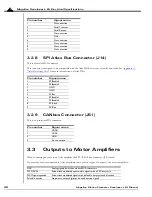
This group of signals, along with ground connections, are available at J14, and comprise an interface directly
compatible with the Atlas Developer’s Kit cards. See
Appendix A, “Atlas Developer’s Kit”
for a complete description
of the Atlas DK system. See
for a detailed description of J14, the SPI Atlas bus
connector.
2.4.6
Pulse and Direction Out
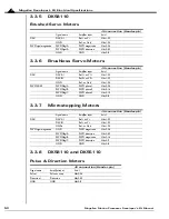
For pulse & direction amplifiers these signals provide an output stream of pulse and direction data compatible with a
wide variety of off-the-shelf step motor amplifiers. These signals are directly generated by the Magellan motion
processor. For more information on output waveforms, pulse rates, and related information, see the
Magellan Motion
Processor User’s Guide,
“Open Loop Stepper Control.”
These signals are named
pulse1-4, direction1-4
.
The default value, upon powerup, for all pulse & direction output signals is high.
Connections & Associated Signals
This group of signals are direct single-signal digital outputs. There are no associated connections that need to be made
for these signals to function properly; however, one or more of the digital grounds must be connected.
Chapter 3, “Magellan Developer’s Kit Electrical Specifications”
for a complete description of the pinout
connections to/from the card.
2.4.7
PWM Out
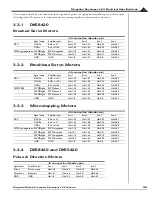
For servo or microstepping motors these signals provide PWM (pulse width modulated) motor command signals
when the motor output mode is set to
PWMSignMagnitude
or
PWM5050Magnitude
. See the
Magellan Motion Processor
User’s Guide
for complete information. The number of signals per axis varies depending on the motor type being
connected to, the number of phases that the motor has, and the motor drive method (sign/magnitude or 50/50).

