background image


SalesIdeasUniverse@gmail.com


Note in the diagram is the same on the pi board, pins are arranged in 2 columns of 20 pins each.  
These instructions will reference the left column or the right column of pins. 

The red wire is connected to the 5v pin (right column, 1

st

(top) pin in the diagram).  The black 

wire is connected to the ground pin (right column, 3

rd

 pin down marked ground). 

OLED Display 

For the OLED, this is a standard serial display SDD1306 4-pin.  The 4 wires are pre-connected to 
the back of the OLED and can be any colour we choose that is available to us when your case is 
assembled so colour does not matter.  What is important is the connection of the appropriate 
pins from the OLED to the pi header. 

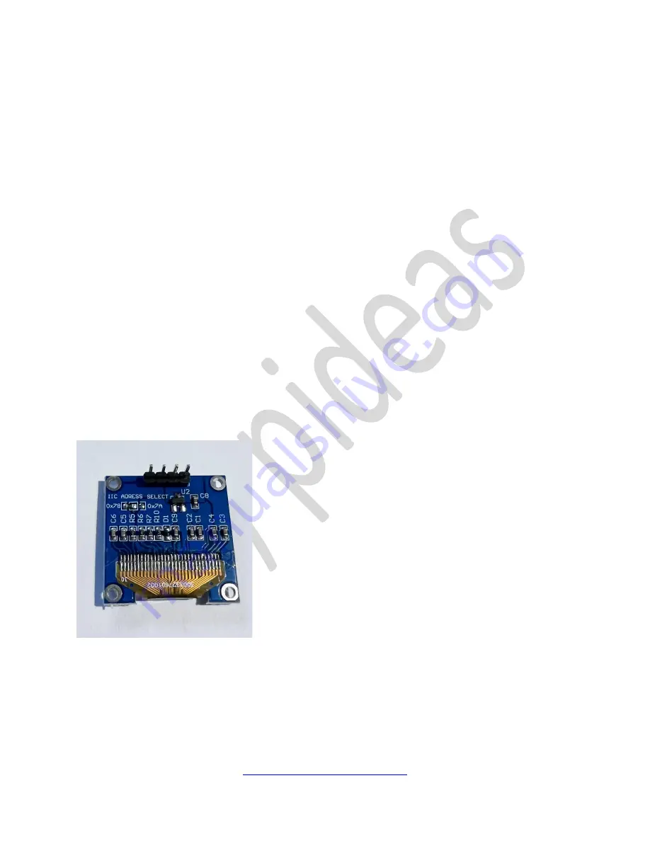
If you look inside the case at the rear of the OLED it will look like either one of the photos below 
but will have the cable fitted. 

THIS IS REALLY IMPORTANT 

 based on the suppliers we used, the wiring 

sequence can be different 

 type 1 or type 2.  Look at the OLED to establish which type it is.  

Note that it’s the position of the VCC and GND are different for pins 3 and 4!


Type 1: 


Look at the back of the OLED as above, the pins are (from left to right in order): 

1.


SDA (seral data) 

2.


SCL (serial clock) 

3.


VCC (3.3v) 

4.


GND (ground) 

Summary of Contents for pi 3B

Page 1: ...the panels are not the same on one side the slot hole is lower than the other It should be high slot on the left side and low slot on the right side This is so the slots align with the pi s header pi...

Page 2: ...o sets of wires 3 wires for the RGB 5v fan and 4 wires for the standard SSD 1306 OLED display Wiring RGB Fan Firstly connect the 5v RGB Fan There are three wires from the fan only two are used the red...

Page 3: ...e any colour we choose that is available to us when your case is assembled so colour does not matter What is important is the connection of the appropriate pins from the OLED to the pi header If you l...

Page 4: ...m Take the VCC wire and insert into the left column 1st pin down 3 3v in the diagram Take the GND wire and insert into the right column 7th pin down Ground in the diagram Note that the OLED uses 3 3v...

Page 5: ...n GPIO 3 Serial Clock I2C in the diagram Take the GND wire and insert into the right column 7th pin down Ground in the diagram Take the VCC wire and insert into the left column 1st pin down 3 3v in th...

Page 6: ...update sudo apt get full upgrade sudo reboot When system rebooted sudo apt get install python3 pip sudo pip3 install upgrade setuptools Install update Dependency Libraries The following libraries may...

Page 7: ...so the most likely issue is wiring Install OLED Python Library To install the library sudo pip3 install adafruit circuitpython ssd1306 sudo apt get install python3 pil Python Stats Script From you pi...

Page 8: ...pi s SD card after your pi is installed the front panel is removable It is held into place by a bracket that is fitted to the top bolts of the fan on the inside of the case To remove the front cover...

Page 9: ...ty of the SD Card sudo raspi config There will be a resulting menu where you should click on the expand filesystem option When you confirm the choice and wait you will receive a notification that the...

Reviews: