17
Serial Stream Object Parameters (Class Code 64):
1)
Baud Rate:
The serial channel RS232 baud rate ranges from 300 ~ 57600 bits/sec.
The acceptable baud rate are 300, 1200, 2400, 4800, 9600, 19200, 38400, and
57600. The baud rate should be set to match the serial connection.
2)
Data Bits:
The number of data bits can be selected at 7 or 8 bits. The data bits
should be set to match the serial connection.
3)
Parity:
The parity bit can be selected at None, Odd, Even, Mark or Space. The
parity bit should be set to match the serial connection.
None = no parity
Odd = parity bit =1, if there are odd number of one in data size
Even = parity bit =1, if there are even number of ones data size.
Mark = parity bit is 1 always
Space = parity bit is 0 always
In most applications, parity bit is set at None (no parity).
4)
Stop Bits:
The stop bits can be selected at 1 or 2. Each data byte (character)
transmitted in a sequence is followed by 1 or 2 extra zero bits. The extra “0” is
marked at the end of a character transmission. In most applications, the stop bit is
set at 1. The stop bits should be set to match the serial connection.
1 = Each data byte (character) transmit is followed by one zero (0).
2 = Each data byte (character) transmit is followed by two zeros (0).
5)
Flow Control:
The flow control can be set at 0, 1, or 2. When flow control is set
to 1, the X-Off (CTRL S) will force the CDN366’s transmit function to block.
The transmitted characters are stored in the FIFO buffer until transmission is re-
enable by sending the X-On (CTRL Q) character to the CDN366. When the
receive FIFO buffer is full, the X-Off character is transmitted to the RS232
interface. The X-On/ X-Off flow control characters are extracted from the data
stream. Therefore, this setting is unsuitable for making binary data transmissions.
When flow control is set to 2, the RTS (pin 7) and CTS (pin 8) control signals are
enabled. The data is transmitted only when the CTS signal asserts a high/low
voltage. When the receive FIFO buffer is not full, the RTS signal is asserted to
allow data reception.
0 = No flow control
1 = X-On/X-Off flow control (software flow control)
2 = CTS / RTS flow control (hardware flow control)
In most applications, the flow control is set to 0 (no flow control).
Summary of Contents for CDN366
Page 1: ...CDN366 DeviceNet Gateway Application Notes ...
Page 3: ...3 Revision Initial Release 6 12 01 ...
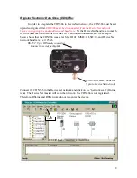
Page 10: ...10 Select Register a single file and enter the EDS file name on the white box Click on Next ...
Page 39: ...39 CDN366 Template Class Instance Attribute Default Setting Unit Comments ...
Page 72: ...DeviceNet RS 232 Interface Module 27 Publication 1770 5 6 June 1996 ...


